
 SUCHEN SIE DIE PASSENDE
INDUSTRIELLE LÖSUNG?
Entdecken Sie Embedded-, Kommunikations- und Automatisierungslösungen für Ihre Anwendung.
_rgb_96dpi_500x500.jpg)
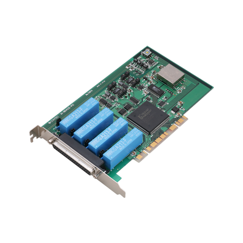
ADI12-16(PCI)
PCI isolated AD card 50kS/s 12 Bit 16 channels + 4*DI + 4*DO
690,00 EUR
inkl. Umsatzsteuer 821,10 EUR
- Bus Isolation via Optocouplers:
Complete electrical isolation between the PC and external I/O circuits ensures high noise immunity and protection against ground loops.
- Flexible Analog Input Configuration:
Supports 16 single‑ended or 8 differential analog input channels, selectable via onboard jumpers. Input ranges include both bipolar (±1.25 V, ±2.5 V, ±5 V, ±10 V) and unipolar (0–1.25 V, 0–2.5 V, 0–5 V, 0–10 V) voltage ranges, as well as 4–20 mA current input.
- High‑Speed 12‑bit A/D Conversion:
Conversion speed up to 20 µs per channel (50 kS/s aggregate), suitable for medium‑speed data acquisition and control applications.
- Large Onboard Buffer Memory:
256 k‑word buffer configurable as FIFO or ring memory, enabling continuous or cyclic sampling independent of host CPU load.
- Advanced Sampling Control:
Sampling can be triggered or stopped by software, external digital signals, or analog level comparison. Internal or external sampling clocks are selectable.
- Optically Isolated Digital I/O:
Four optocoupler‑isolated digital inputs and four open‑collector digital outputs (sink type), each with ≤ 1 ms response time, allow safe interfacing with external control devices.
- Software‑Based Calibration:
Full calibration of analog input channels can be performed via software, with user‑defined adjustment data stored for environmental compensation.
- Comprehensive Software Support:
Includes Windows and Linux driver libraries (API‑PAC(W32)), sample programs for Visual Basic, Visual C++, C#, Delphi, and gcc, and LabVIEW VI‑DAQ support.
- Optional Accessories and Expansion:
Wide range of optional cables, termination panels, and signal conditioning modules (e.g., low‑pass filters, isolation amplifiers, BNC panels).
Complete electrical isolation between the PC and external I/O circuits ensures high noise immunity and protection against ground loops.
- Flexible Analog Input Configuration:
Supports 16 single‑ended or 8 differential analog input channels, selectable via onboard jumpers. Input ranges include both bipolar (±1.25 V, ±2.5 V, ±5 V, ±10 V) and unipolar (0–1.25 V, 0–2.5 V, 0–5 V, 0–10 V) voltage ranges, as well as 4–20 mA current input.
- High‑Speed 12‑bit A/D Conversion:
Conversion speed up to 20 µs per channel (50 kS/s aggregate), suitable for medium‑speed data acquisition and control applications.
- Large Onboard Buffer Memory:
256 k‑word buffer configurable as FIFO or ring memory, enabling continuous or cyclic sampling independent of host CPU load.
- Advanced Sampling Control:
Sampling can be triggered or stopped by software, external digital signals, or analog level comparison. Internal or external sampling clocks are selectable.
- Optically Isolated Digital I/O:
Four optocoupler‑isolated digital inputs and four open‑collector digital outputs (sink type), each with ≤ 1 ms response time, allow safe interfacing with external control devices.
- Software‑Based Calibration:
Full calibration of analog input channels can be performed via software, with user‑defined adjustment data stored for environmental compensation.
- Comprehensive Software Support:
Includes Windows and Linux driver libraries (API‑PAC(W32)), sample programs for Visual Basic, Visual C++, C#, Delphi, and gcc, and LabVIEW VI‑DAQ support.
- Optional Accessories and Expansion:
Wide range of optional cables, termination panels, and signal conditioning modules (e.g., low‑pass filters, isolation amplifiers, BNC panels).
Comprehensive Product Summary – ADI12‑16(PCI) PCI Isolated Analog‑to‑Digital Conversion Board
### 1. Product Overview
Product Name: PCI Isolated Analog Input Board
Model: ADI12‑16(PCI)
Series: ADI12 Series – Isolated Multi‑Function Analog Input Boards
Article Number: ADI12‑16(PCI)
Manufacturer: CONTEC Co., Ltd., Osaka, Japan
Product Description:
The ADI12‑16(PCI) is a high‑performance, bus‑isolated analog‑to‑digital (A/D) conversion interface board designed for PCI bus systems. It provides 12‑bit resolution, 16 single‑ended or 8 differential analog input channels, and optically isolated digital I/O (4 inputs and 4 outputs). The board supports a maximum sampling rate of 50 kS/s (20 µs per channel) and includes a 256 k‑word FIFO or ring buffer memory. It is compatible with Windows and Linux operating systems and supports LabVIEW through the VI‑DAQ library.
### 2. Key Features
- Bus Isolation via Optocouplers:
Complete electrical isolation between the PC and external I/O circuits ensures high noise immunity and protection against ground loops.
- Flexible Analog Input Configuration:
Supports 16 single‑ended or 8 differential analog input channels, selectable via onboard jumpers. Input ranges include both bipolar (±1.25 V, ±2.5 V, ±5 V, ±10 V) and unipolar (0–1.25 V, 0–2.5 V, 0–5 V, 0–10 V) voltage ranges, as well as 4–20 mA current input.
- High‑Speed 12‑bit A/D Conversion:
Conversion speed up to 20 µs per channel (50 kS/s aggregate), suitable for medium‑speed data acquisition and control applications.
- Large Onboard Buffer Memory:
256 k‑word buffer configurable as FIFO or ring memory, enabling continuous or cyclic sampling independent of host CPU load.
- Advanced Sampling Control:
Sampling can be triggered or stopped by software, external digital signals, or analog level comparison. Internal or external sampling clocks are selectable.
- Optically Isolated Digital I/O:
Four optocoupler‑isolated digital inputs and four open‑collector digital outputs (sink type), each with ≤ 1 ms response time, allow safe interfacing with external control devices.
- Software‑Based Calibration:
Full calibration of analog input channels can be performed via software, with user‑defined adjustment data stored for environmental compensation.
- Comprehensive Software Support:
Includes Windows and Linux driver libraries (API‑PAC(W32)), sample programs for Visual Basic, Visual C++, C#, Delphi, and gcc, and LabVIEW VI‑DAQ support.
- Optional Accessories and Expansion:
Wide range of optional cables, termination panels, and signal conditioning modules (e.g., low‑pass filters, isolation amplifiers, BNC panels).
### 3. Technical Specifications
| Parameter | Specification |
|----------------|------------------|
| Bus Interface | PCI, 32‑bit, 33 MHz, 5 V signaling |
| Isolation | Bus‑isolated via optocouplers |
| Analog Input Channels | 16 (single‑ended) / 8 (differential) |
| Input Type | Voltage or current (jumper‑selectable) |
| Input Ranges | Bipolar: ±10 V, ±5 V, ±2.5 V, ±1.25 V<br>Unipolar: 0–10 V, 0–5 V, 0–2.5 V, 0–1.25 V<br>Current: 4–20 mA |
| Absolute Max Input Voltage | ±20 V (voltage input) |
| Absolute Max Input Current | 25 mA (current input) |
| Input Impedance | ≥ 1 MΩ (voltage input) |
| Resolution | 12 bits (4096 steps) |
| Non‑Linearity Error | ±2 LSB (±10 V, ±5 V, 0–10 V, 0–5 V)<br>±4 LSB (±2.5 V, ±1.25 V, 0–2.5 V, 0–1.25 V)<br>±3 LSB (4–20 mA) |
| Conversion Speed | 20 µs/channel (max) |
| Buffer Memory | 256 k‑word FIFO or ring (software‑selectable) |
| Conversion Start Trigger | Software / input data comparison / isolated external digital input |
| Conversion Stop Trigger | Sampling count / input data comparison / external digital input / software |
| Digital Inputs | 4 channels, optocoupler‑isolated (sink‑type compatible), ≤ 1 ms response |
| Digital Outputs | 4 channels, optocoupler‑isolated open‑collector (sink type), ≤ 1 ms response, 100 mA max per point, 2 A max per common |
| Connectors | CN1: 37‑pin D‑SUB female (#4‑40 UNC)<br>CN2: 16‑pin pin‑header |
| I/O Address Range | 16 ports boundary |
| Interrupts | 1 level (enable/disable selectable) |
| Power Consumption | +5 V ±5 %, 1.2 A max |
| Operating Temperature | 0 – 50 °C |
| Operating Humidity | 10 – 90 % RH (non‑condensing) |
| Dimensions | 176.41 mm (L) × 106.68 mm (H) |
| Weight | Approx. 160 g |
*Note:* Non‑linearity may increase near 0 °C or 50 °C; recalibration under actual conditions is recommended.
### 4. Functionality
Operating Principle:
The ADI12‑16(PCI) converts analog voltage or current signals into 12‑bit digital data through a multiplexed A/D converter. The board’s optically isolated interface ensures signal integrity and protection from electrical noise. Data is stored in onboard memory and transferred to the host PC via the PCI bus.
Use Cases and Applications:
- Industrial process monitoring and control
- Laboratory data acquisition
- Sensor and transducer signal digitization
- Automated test systems
- Embedded measurement in PC‑based instrumentation
Compatibility:
- Operating Systems: Windows 7/Vista/XP/Server 2003/2000, Red Hat Linux, Turbo Linux
- Programming Languages: Visual Basic, Visual C++, Visual C#, Delphi, C++ Builder, gcc
- Software Environments: LabVIEW (via VI‑DAQ library)
Sampling Control:
- Internal or external clock selectable
- Start/stop triggers via software, external digital input, or analog level comparison
- Supports delayed sampling and event‑driven acquisition
Digital I/O Functionality:
- Input circuits accept 12–24 V DC current‑driven devices (approx. 8 mA @ 24 V)
- Output circuits drive relays, LEDs, or TTL inputs (100 mA max per channel)
- External power supply required for digital I/O operation
### 5. Components & Accessories
Included Items (Standard Package):
- ADI12‑16(PCI) board × 1
- First‑step guide × 1
- CD‑ROM (API‑PAC(W32)) × 1 – includes drivers, utilities, and user’s guide
Optional Cables:
- PCA37P‑1.5 (1.5 m) – Flat cable, 1 × 37‑pin D‑SUB
- PCA37PS‑0.5P / 1.5P – Shielded 37‑pin D‑SUB cables
- PCB37PS‑0.5P / 1.5P – Dual 37‑pin shielded cables
- PCC16PS‑1.5 / 3 – Coaxial cables for single‑ended inputs
- PCD8PS‑1.5 / 3 – Two‑wire shielded cables for differential inputs
- DT/E1 – Flat cable with 16‑pin header
- DT‑E3 – Conversion cable (16‑pin to 15‑pin with bracket)
Optional Connectors:
- CN5‑D37M – 37‑pin male connector set (5 pcs)
Optional Accessories:
- DTP‑3A / DTP‑4A – Termination panels with screw terminals
- EPD‑37 / EPD‑37A – Screw terminal panels (M3/M3.5)
- FTP‑15 – Digital I/O termination panel
- ATP‑16 – BNC termination panel for 16 analog inputs
- ATII‑8C – 8‑channel isolation accessory board
- ATLF‑8A – Low‑pass filter expansion board
- ATBA‑16E – Buffer amplifier termination panel
(*Some accessories require optional cables or external power supplies.*)
### 6. Installation & Setup
Hardware Setup Steps:
1. Software Installation:
Install the API‑PAC(W32) driver library before inserting the board.
2. Board Configuration:
- Set board ID (0–Fh) via rotary switch SW1.
- Configure interrupt usage (JP22).
- Select input mode (single‑ended/differential) via JP11–JP13.
- Set input range and type (voltage/current) via JP14–JP21.
3. Physical Installation:
Power off the PC, insert the board into a PCI slot, and secure with a screw.
4. Driver Initialization:
Use Device Manager (Windows) or configuration scripts (Linux) to register the device.
5. Verification:
Run the included diagnostic utility to confirm proper operation.
Connection Interfaces:
- CN1 (37‑pin D‑SUB): Analog input signals
- CN2 (16‑pin header): Digital I/O and control signals (start/stop triggers, sampling clock)
Environmental Requirements:
Operate within 0–50 °C and 10–90 % RH (non‑condensing). Avoid corrosive gases and excessive dust.
### 7. Performance & Capabilities
- Sampling Rate: Up to 50 kS/s (20 µs/channel)
- Resolution: 12 bits (4096 quantization levels)
- Input Accuracy: ±2–4 LSB depending on range
- Buffer Capacity: 256 k samples (FIFO or ring)
- Digital I/O Response: ≤ 1 ms
- Output Drive: 100 mA per channel (2 A per common)
- Noise Immunity: High, due to optocoupler isolation and differential input option
- Limitations: Not suitable for high‑frequency (> 1 MHz) analog signals; cross‑talk may occur if signal sources exceed 1 MHz or cable lengths are excessive.
### 8. Standards & Compliance
- Bus Standard: PCI 2.2 compliant (32‑bit, 33 MHz, 5 V)
- Isolation: Optocoupler‑based bus isolation between PC and I/O circuits
- Environmental Compliance: Designed for CE EMC Directive compliance when used with shielded cables
- Safety: Meets CONTEC internal safety and reliability standards
- Operating System Support: Windows 7/Vista/XP/Server 2003/2000, Linux (Red Hat, Turbo Linux)
- Software Libraries: API‑AIO(WDM), API‑AIO(98/PC), API‑AIO(LNX), LabVIEW VI‑DAQ
### 9. Additional Information
Warranty:
Limited 3‑year warranty covering defects in materials and workmanship. Excludes damage from misuse, modification, or environmental exposure.
Technical Support:
- Website: [https://www.contec.com](https://www.contec.com)
- Resources: Driver updates, manuals, sample programs, and technical documentation available online.
Maintenance & Calibration:
- Factory‑calibrated prior to shipment.
- Software‑based recalibration supported for environmental drift compensation.
- Periodic inspection recommended to ensure connector integrity and cleanliness.
Software Tools & Utilities:
- API‑PAC(W32): Comprehensive driver library with diagnostic and sample programs.
- API‑AIO(WDM): Modern Windows driver supporting event‑driven I/O.
- API‑AIO(98/PC): Legacy driver for older Windows systems.
- API‑AIO(LNX): Linux driver with shared library and kernel module.
- VI‑DAQ: LabVIEW library for simplified integration.
Sample Programs:
Demonstrations for analog input/output, digital I/O, and trigger‑based acquisition are provided in multiple languages.
Uninstallation:
Drivers can be removed via Windows Control Panel or Linux uninstall scripts.
Safety & Handling:
- Do not install/remove the board with power applied.
- Avoid touching gold‑plated edge connectors.
- Use shielded cables to maintain EMC compliance.
- Ensure adequate PC power supply capacity (+5 V @ 1.2 A max).
### Summary
The CONTEC ADI12‑16(PCI) is a robust, isolated analog input board engineered for precise, medium‑speed data acquisition in PCI‑based systems. With 12‑bit resolution, flexible input configurations, and optically isolated digital I/O, it provides reliable performance in industrial, laboratory, and embedded measurement environments. Its 256 k‑word buffer, software‑configurable triggers, and comprehensive driver support make it ideal for applications requiring stable, noise‑immune analog data capture and control.
The board’s compatibility with Windows, Linux, and LabVIEW, combined with extensive optional accessories and a 3‑year warranty, ensures long‑term usability and integration flexibility in diverse automation and instrumentation systems.
### 1. Product Overview
Product Name: PCI Isolated Analog Input Board
Model: ADI12‑16(PCI)
Series: ADI12 Series – Isolated Multi‑Function Analog Input Boards
Article Number: ADI12‑16(PCI)
Manufacturer: CONTEC Co., Ltd., Osaka, Japan
Product Description:
The ADI12‑16(PCI) is a high‑performance, bus‑isolated analog‑to‑digital (A/D) conversion interface board designed for PCI bus systems. It provides 12‑bit resolution, 16 single‑ended or 8 differential analog input channels, and optically isolated digital I/O (4 inputs and 4 outputs). The board supports a maximum sampling rate of 50 kS/s (20 µs per channel) and includes a 256 k‑word FIFO or ring buffer memory. It is compatible with Windows and Linux operating systems and supports LabVIEW through the VI‑DAQ library.
### 2. Key Features
- Bus Isolation via Optocouplers:
Complete electrical isolation between the PC and external I/O circuits ensures high noise immunity and protection against ground loops.
- Flexible Analog Input Configuration:
Supports 16 single‑ended or 8 differential analog input channels, selectable via onboard jumpers. Input ranges include both bipolar (±1.25 V, ±2.5 V, ±5 V, ±10 V) and unipolar (0–1.25 V, 0–2.5 V, 0–5 V, 0–10 V) voltage ranges, as well as 4–20 mA current input.
- High‑Speed 12‑bit A/D Conversion:
Conversion speed up to 20 µs per channel (50 kS/s aggregate), suitable for medium‑speed data acquisition and control applications.
- Large Onboard Buffer Memory:
256 k‑word buffer configurable as FIFO or ring memory, enabling continuous or cyclic sampling independent of host CPU load.
- Advanced Sampling Control:
Sampling can be triggered or stopped by software, external digital signals, or analog level comparison. Internal or external sampling clocks are selectable.
- Optically Isolated Digital I/O:
Four optocoupler‑isolated digital inputs and four open‑collector digital outputs (sink type), each with ≤ 1 ms response time, allow safe interfacing with external control devices.
- Software‑Based Calibration:
Full calibration of analog input channels can be performed via software, with user‑defined adjustment data stored for environmental compensation.
- Comprehensive Software Support:
Includes Windows and Linux driver libraries (API‑PAC(W32)), sample programs for Visual Basic, Visual C++, C#, Delphi, and gcc, and LabVIEW VI‑DAQ support.
- Optional Accessories and Expansion:
Wide range of optional cables, termination panels, and signal conditioning modules (e.g., low‑pass filters, isolation amplifiers, BNC panels).
### 3. Technical Specifications
| Parameter | Specification |
|----------------|------------------|
| Bus Interface | PCI, 32‑bit, 33 MHz, 5 V signaling |
| Isolation | Bus‑isolated via optocouplers |
| Analog Input Channels | 16 (single‑ended) / 8 (differential) |
| Input Type | Voltage or current (jumper‑selectable) |
| Input Ranges | Bipolar: ±10 V, ±5 V, ±2.5 V, ±1.25 V<br>Unipolar: 0–10 V, 0–5 V, 0–2.5 V, 0–1.25 V<br>Current: 4–20 mA |
| Absolute Max Input Voltage | ±20 V (voltage input) |
| Absolute Max Input Current | 25 mA (current input) |
| Input Impedance | ≥ 1 MΩ (voltage input) |
| Resolution | 12 bits (4096 steps) |
| Non‑Linearity Error | ±2 LSB (±10 V, ±5 V, 0–10 V, 0–5 V)<br>±4 LSB (±2.5 V, ±1.25 V, 0–2.5 V, 0–1.25 V)<br>±3 LSB (4–20 mA) |
| Conversion Speed | 20 µs/channel (max) |
| Buffer Memory | 256 k‑word FIFO or ring (software‑selectable) |
| Conversion Start Trigger | Software / input data comparison / isolated external digital input |
| Conversion Stop Trigger | Sampling count / input data comparison / external digital input / software |
| Digital Inputs | 4 channels, optocoupler‑isolated (sink‑type compatible), ≤ 1 ms response |
| Digital Outputs | 4 channels, optocoupler‑isolated open‑collector (sink type), ≤ 1 ms response, 100 mA max per point, 2 A max per common |
| Connectors | CN1: 37‑pin D‑SUB female (#4‑40 UNC)<br>CN2: 16‑pin pin‑header |
| I/O Address Range | 16 ports boundary |
| Interrupts | 1 level (enable/disable selectable) |
| Power Consumption | +5 V ±5 %, 1.2 A max |
| Operating Temperature | 0 – 50 °C |
| Operating Humidity | 10 – 90 % RH (non‑condensing) |
| Dimensions | 176.41 mm (L) × 106.68 mm (H) |
| Weight | Approx. 160 g |
*Note:* Non‑linearity may increase near 0 °C or 50 °C; recalibration under actual conditions is recommended.
### 4. Functionality
Operating Principle:
The ADI12‑16(PCI) converts analog voltage or current signals into 12‑bit digital data through a multiplexed A/D converter. The board’s optically isolated interface ensures signal integrity and protection from electrical noise. Data is stored in onboard memory and transferred to the host PC via the PCI bus.
Use Cases and Applications:
- Industrial process monitoring and control
- Laboratory data acquisition
- Sensor and transducer signal digitization
- Automated test systems
- Embedded measurement in PC‑based instrumentation
Compatibility:
- Operating Systems: Windows 7/Vista/XP/Server 2003/2000, Red Hat Linux, Turbo Linux
- Programming Languages: Visual Basic, Visual C++, Visual C#, Delphi, C++ Builder, gcc
- Software Environments: LabVIEW (via VI‑DAQ library)
Sampling Control:
- Internal or external clock selectable
- Start/stop triggers via software, external digital input, or analog level comparison
- Supports delayed sampling and event‑driven acquisition
Digital I/O Functionality:
- Input circuits accept 12–24 V DC current‑driven devices (approx. 8 mA @ 24 V)
- Output circuits drive relays, LEDs, or TTL inputs (100 mA max per channel)
- External power supply required for digital I/O operation
### 5. Components & Accessories
Included Items (Standard Package):
- ADI12‑16(PCI) board × 1
- First‑step guide × 1
- CD‑ROM (API‑PAC(W32)) × 1 – includes drivers, utilities, and user’s guide
Optional Cables:
- PCA37P‑1.5 (1.5 m) – Flat cable, 1 × 37‑pin D‑SUB
- PCA37PS‑0.5P / 1.5P – Shielded 37‑pin D‑SUB cables
- PCB37PS‑0.5P / 1.5P – Dual 37‑pin shielded cables
- PCC16PS‑1.5 / 3 – Coaxial cables for single‑ended inputs
- PCD8PS‑1.5 / 3 – Two‑wire shielded cables for differential inputs
- DT/E1 – Flat cable with 16‑pin header
- DT‑E3 – Conversion cable (16‑pin to 15‑pin with bracket)
Optional Connectors:
- CN5‑D37M – 37‑pin male connector set (5 pcs)
Optional Accessories:
- DTP‑3A / DTP‑4A – Termination panels with screw terminals
- EPD‑37 / EPD‑37A – Screw terminal panels (M3/M3.5)
- FTP‑15 – Digital I/O termination panel
- ATP‑16 – BNC termination panel for 16 analog inputs
- ATII‑8C – 8‑channel isolation accessory board
- ATLF‑8A – Low‑pass filter expansion board
- ATBA‑16E – Buffer amplifier termination panel
(*Some accessories require optional cables or external power supplies.*)
### 6. Installation & Setup
Hardware Setup Steps:
1. Software Installation:
Install the API‑PAC(W32) driver library before inserting the board.
2. Board Configuration:
- Set board ID (0–Fh) via rotary switch SW1.
- Configure interrupt usage (JP22).
- Select input mode (single‑ended/differential) via JP11–JP13.
- Set input range and type (voltage/current) via JP14–JP21.
3. Physical Installation:
Power off the PC, insert the board into a PCI slot, and secure with a screw.
4. Driver Initialization:
Use Device Manager (Windows) or configuration scripts (Linux) to register the device.
5. Verification:
Run the included diagnostic utility to confirm proper operation.
Connection Interfaces:
- CN1 (37‑pin D‑SUB): Analog input signals
- CN2 (16‑pin header): Digital I/O and control signals (start/stop triggers, sampling clock)
Environmental Requirements:
Operate within 0–50 °C and 10–90 % RH (non‑condensing). Avoid corrosive gases and excessive dust.
### 7. Performance & Capabilities
- Sampling Rate: Up to 50 kS/s (20 µs/channel)
- Resolution: 12 bits (4096 quantization levels)
- Input Accuracy: ±2–4 LSB depending on range
- Buffer Capacity: 256 k samples (FIFO or ring)
- Digital I/O Response: ≤ 1 ms
- Output Drive: 100 mA per channel (2 A per common)
- Noise Immunity: High, due to optocoupler isolation and differential input option
- Limitations: Not suitable for high‑frequency (> 1 MHz) analog signals; cross‑talk may occur if signal sources exceed 1 MHz or cable lengths are excessive.
### 8. Standards & Compliance
- Bus Standard: PCI 2.2 compliant (32‑bit, 33 MHz, 5 V)
- Isolation: Optocoupler‑based bus isolation between PC and I/O circuits
- Environmental Compliance: Designed for CE EMC Directive compliance when used with shielded cables
- Safety: Meets CONTEC internal safety and reliability standards
- Operating System Support: Windows 7/Vista/XP/Server 2003/2000, Linux (Red Hat, Turbo Linux)
- Software Libraries: API‑AIO(WDM), API‑AIO(98/PC), API‑AIO(LNX), LabVIEW VI‑DAQ
### 9. Additional Information
Warranty:
Limited 3‑year warranty covering defects in materials and workmanship. Excludes damage from misuse, modification, or environmental exposure.
Technical Support:
- Website: [https://www.contec.com](https://www.contec.com)
- Resources: Driver updates, manuals, sample programs, and technical documentation available online.
Maintenance & Calibration:
- Factory‑calibrated prior to shipment.
- Software‑based recalibration supported for environmental drift compensation.
- Periodic inspection recommended to ensure connector integrity and cleanliness.
Software Tools & Utilities:
- API‑PAC(W32): Comprehensive driver library with diagnostic and sample programs.
- API‑AIO(WDM): Modern Windows driver supporting event‑driven I/O.
- API‑AIO(98/PC): Legacy driver for older Windows systems.
- API‑AIO(LNX): Linux driver with shared library and kernel module.
- VI‑DAQ: LabVIEW library for simplified integration.
Sample Programs:
Demonstrations for analog input/output, digital I/O, and trigger‑based acquisition are provided in multiple languages.
Uninstallation:
Drivers can be removed via Windows Control Panel or Linux uninstall scripts.
Safety & Handling:
- Do not install/remove the board with power applied.
- Avoid touching gold‑plated edge connectors.
- Use shielded cables to maintain EMC compliance.
- Ensure adequate PC power supply capacity (+5 V @ 1.2 A max).
### Summary
The CONTEC ADI12‑16(PCI) is a robust, isolated analog input board engineered for precise, medium‑speed data acquisition in PCI‑based systems. With 12‑bit resolution, flexible input configurations, and optically isolated digital I/O, it provides reliable performance in industrial, laboratory, and embedded measurement environments. Its 256 k‑word buffer, software‑configurable triggers, and comprehensive driver support make it ideal for applications requiring stable, noise‑immune analog data capture and control.
The board’s compatibility with Windows, Linux, and LabVIEW, combined with extensive optional accessories and a 3‑year warranty, ensures long‑term usability and integration flexibility in diverse automation and instrumentation systems.
-
 ds_adi1216pci_en.pdf
PDF Catalog
ds_adi1216pci_en.pdf
PDF Catalog
-
.webp) man_ADI12-16(PCI).pdf
Manual
man_ADI12-16(PCI).pdf
Manual
Kein Zubehör vorhanden.
l_rgb_96dpi_500x500.jpg)
l_conn_rgb_96dpi_500x500.jpg)