SUCHEN SIE DIE PASSENDE
INDUSTRIELLE LÖSUNG?
Entdecken Sie Embedded-, Kommunikations- und Automatisierungslösungen für Ihre Anwendung.
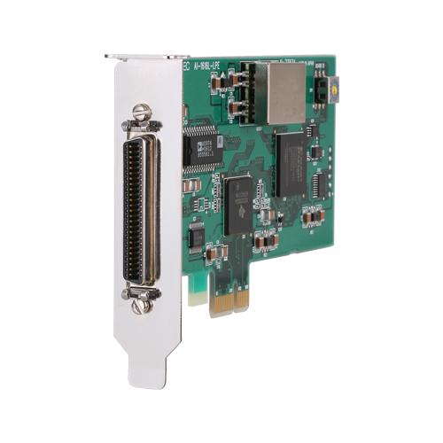
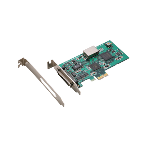
AI-1616L-LPE
PCIe Low Profile AD 100kS/s 16 Bit 16 CH + 4*DI + 4*DO + Cnt
290,00 EUR
inkl. Umsatzsteuer 345,10 EUR
- High‑precision analog input: 16 single‑ended channels, 16‑bit resolution, bipolar ±10 V input range, 100 kS/s (10 µs/channel) conversion rate.
- Digital I/O: 4 TTL‑level inputs + 4 TTL‑level outputs (positive logic).
- Counter: 1 channel, 32‑bit up‑counter, max frequency 10 MHz (1 MHz for isolated variant).
- Buffer memory: 1 k‑word onboard FIFO/RING buffer enabling background sampling independent of host CPU load.
- Trigger and clock control: Sampling start/stop selectable by software command, external trigger, or comparison of conversion data; internal or external sampling clock.
- Digital filter: 1 µs software‑selectable filter suppresses chattering on external trigger, sampling clock, digital input, and counter signals.
- Software calibration: All analog calibration performed in software; user can store additional adjustment data to compensate for environmental drift.
- Bus isolation (variant AI‑1616LI‑PE): Digital isolator separates PC bus from external I/O circuits, improving noise immunity.
- Compatibility: Connector and function compatible with legacy PCI ADI16‑16(LPCI)L boards, simplifying migration.
- Comprehensive software support: Windows and Linux drivers, C‑LOGGER data‑logger, MATLAB ML‑DAQ library, and LabVIEW VI‑DAQ plug‑ins.
- Low‑profile PCI Express x1 interface: Compliant with PCI Express Base Specification Rev 1.0a; fits compact industrial PCs.
- Operating environment: 0 – 50 °C, 10 – 90 % RH (non‑condensing).
- Digital I/O: 4 TTL‑level inputs + 4 TTL‑level outputs (positive logic).
- Counter: 1 channel, 32‑bit up‑counter, max frequency 10 MHz (1 MHz for isolated variant).
- Buffer memory: 1 k‑word onboard FIFO/RING buffer enabling background sampling independent of host CPU load.
- Trigger and clock control: Sampling start/stop selectable by software command, external trigger, or comparison of conversion data; internal or external sampling clock.
- Digital filter: 1 µs software‑selectable filter suppresses chattering on external trigger, sampling clock, digital input, and counter signals.
- Software calibration: All analog calibration performed in software; user can store additional adjustment data to compensate for environmental drift.
- Bus isolation (variant AI‑1616LI‑PE): Digital isolator separates PC bus from external I/O circuits, improving noise immunity.
- Compatibility: Connector and function compatible with legacy PCI ADI16‑16(LPCI)L boards, simplifying migration.
- Comprehensive software support: Windows and Linux drivers, C‑LOGGER data‑logger, MATLAB ML‑DAQ library, and LabVIEW VI‑DAQ plug‑ins.
- Low‑profile PCI Express x1 interface: Compliant with PCI Express Base Specification Rev 1.0a; fits compact industrial PCs.
- Operating environment: 0 – 50 °C, 10 – 90 % RH (non‑condensing).
Comprehensive Product Summary – CONTEC AI‑1616L‑LPE PCI Express Low‑Profile Analog Input Board
*(Approx. 12 000 characters / ~3000 tokens)*
### 1. Product Overview
Product Name: AI‑1616L‑LPE
Model / Article Number: AI‑1616L‑LPE
Series: Low‑Profile PCI Express Analog I/O Boards (AIO‑160802L‑LPE / AI‑1616L‑LPE / AO‑1604L‑LPE family)
Manufacturer: CONTEC CO., LTD., Osaka Japan
Product Type: High‑resolution 16‑bit analog input interface board for PCI Express x1 bus
The AI‑1616L‑LPE is a multifunction, low‑profile PCI Express data‑acquisition (DAQ) board providing sixteen 16‑bit analog input channels, four digital inputs, four digital outputs, and one 32‑bit counter. It is designed for precision analog signal measurement, process monitoring, and laboratory automation where compact PCI Express form factor and high‑accuracy sampling are required. The board supports both low‑profile and standard PCIe brackets and is supplied with driver libraries and utilities for Windows and Linux.
### 2. Key Features
- High‑precision analog input: 16 single‑ended channels, 16‑bit resolution, bipolar ±10 V input range, 100 kS/s (10 µs/channel) conversion rate.
- Digital I/O: 4 TTL‑level inputs + 4 TTL‑level outputs (positive logic).
- Counter: 1 channel, 32‑bit up‑counter, max frequency 10 MHz (1 MHz for isolated variant).
- Buffer memory: 1 k‑word onboard FIFO/RING buffer enabling background sampling independent of host CPU load.
- Trigger and clock control: Sampling start/stop selectable by software command, external trigger, or comparison of conversion data; internal or external sampling clock.
- Digital filter: 1 µs software‑selectable filter suppresses chattering on external trigger, sampling clock, digital input, and counter signals.
- Software calibration: All analog calibration performed in software; user can store additional adjustment data to compensate for environmental drift.
- Bus isolation (variant AI‑1616LI‑PE): Digital isolator separates PC bus from external I/O circuits, improving noise immunity.
- Compatibility: Connector and function compatible with legacy PCI ADI16‑16(LPCI)L boards, simplifying migration.
- Comprehensive software support: Windows and Linux drivers, C‑LOGGER data‑logger, MATLAB ML‑DAQ library, and LabVIEW VI‑DAQ plug‑ins.
- Low‑profile PCI Express x1 interface: Compliant with PCI Express Base Specification Rev 1.0a; fits compact industrial PCs.
- Operating environment: 0 – 50 °C, 10 – 90 % RH (non‑condensing).
### 3. Technical Specifications
| Parameter | Specification |
|:--|:--|
| Bus Interface | PCI Express Base Spec Rev 1.0a (x1 lane) |
| Analog Inputs | 16 channels, single‑ended (un‑isolated) |
| Input Range | Bipolar ±10 V (absolute max ±20 V) |
| Input Impedance | ≥ 1 MΩ |
| Resolution | 16 bits |
| Non‑linearity error | ±5 LSB (≈ 0.1 % FS at 0–50 °C) |
| Conversion Speed | 10 µs per channel (100 kS/s aggregate) |
| Buffer Memory | 1 k word FIFO or RING |
| Start/Stop Trigger | Software / External TTL (rising or falling edge selectable) |
| External Clock | TTL level input (selectable edge) |
| Digital Inputs | 4 channels TTL positive logic |
| Digital Outputs | 4 channels TTL positive logic |
| Counter | 1 channel 32‑bit up‑counter (FFFF FFFFh max) |
| Counter Inputs | Gate (High level) and Up (rising edge) TTL |
| Counter Output | Count‑match pulse TTL positive logic |
| Response Frequency | 10 MHz max |
| Connector | 50‑pin mini‑ribbon 3M 10250‑52A2JL |
| Power Consumption | +3.3 V 400 mA / +12 V 120 mA (max) |
| Dimensions | 121.69 (L) × 67.90 (H) mm |
| Weight | ≈ 60 g |
| Operating Conditions | 0 – 50 °C, 10 – 90 % RH (no condensation) |
| Storage | Room temperature, dry, no vibration |
| Compliance | CE EMC Directive (compliant when using shielded cable) |
### 4. Functionality and Applications
Operating Principle:
The AI‑1616L‑LPE converts analog voltages from external sensors or instruments into 16‑bit digital data via an onboard A/D converter. Sampling is controlled by internal or external clocks and can be triggered by software or external TTL signals. Data are temporarily stored in the 1 k‑word buffer, then transferred to host memory through the PCI Express bus.
Typical Use Cases:
- Industrial process monitoring and control
- Laboratory data acquisition and waveform logging
- Sensor signal digitization (temperature, pressure, vibration)
- Automated test systems requiring multi‑channel analog input
- Integration with MATLAB or LabVIEW for scientific analysis
Compatibility:
Fully compatible with CONTEC’s API‑AIO driver family and legacy PCI ADI16‑16(LPCI)L pinout. Works with Windows (32/64‑bit) and Linux kernels via supplied drivers.
### 5. Components and Accessories
Standard Package Contents:
- AI‑1616L‑LPE board × 1
- Low‑profile bracket (pre‑installed) and standard bracket × 1
- First Step Guide × 1
- Driver / User’s Guide Disk (API‑PAC W32) × 1
- Warranty Certificate × 1
- Serial Number Label × 1
Optional Cables and Terminal Units:
- PCB50PS‑0.5P (0.5 m) / PCB50PS‑1.5P (1.5 m) – Shielded 50‑pin mini‑ribbon cables (both ends).
- PCA50PS‑0.5P / 1.5P – Shielded cable with one mini‑ribbon connector.
- EPD‑50A – 50‑point M3 screw terminal unit (“spring‑up” type).
- ATBA‑8L / ATBA‑16L – 8 or 16 channel buffer amplifier boxes (requires POA200‑20 AC adapter).
- ATP‑8L – BNC terminal unit for up to 8 analog inputs and 2 outputs.
Connector Pin Summary (CN1 50‑pin):
- AI00–AI15 Analog Inputs
- AGND Analog Ground
- DI00–DI03 Digital Inputs
- DO00–DO03 Digital Outputs
- CNT UPCLK / GATE / OUT Counter signals
- AI START / STOP / EXCLK External trigger and clock inputs
- DGND Digital Ground
- Reserved / N.C. pins must remain unconnected
### 6. Installation and Setup
1. Software Installation: Install the API‑PAC(W32) driver library before inserting the board. Choose API‑AIO(WDM) for Windows or API‑AIO(LNX) for Linux.
2. Hardware Preparation: Power off PC, remove cover, insert board into PCIe x1 slot. Replace low‑profile bracket with standard one if needed.
3. Device Identification: Set Board ID (0–Fh) via rotary switch SW1 when multiple boards are installed.
4. Driver Recognition: Upon boot, Windows detects the device and loads the INF from \INF\WDM\AIO on the disk.
5. Device Naming: Assign a unique device name in Device Manager for use in applications.
6. Verification: Run the diagnostic utility to confirm analog input/output, digital I/O, and counter operation.
Connection Guidelines:
Use shielded cables for long runs or noisy environments. Connect each signal to its corresponding ground. Unused analog inputs should be tied to AGND. Do not short outputs to ground or other outputs. Keep analog and digital grounds separate to minimize noise.
### 7. Performance and Capabilities
- Sampling Rate: 100 k samples per second aggregate (10 µs per channel).
- Resolution and Accuracy: 16‑bit (1 part in 65 536); non‑linearity ±0.1 % FS.
- Input Range: ±10 V bipolar (absolute max ±20 V).
- Buffer Operation: FIFO for continuous acquisition or RING for cyclic logging.
- Trigger Modes: Software, external TTL edge, or level comparison (start/stop independent).
- Clock Sources: Internal oscillator or external TTL clock.
- Counter Performance: 32‑bit up‑count, 10 MHz max input, compare‑match output pulse 1 µs width.
- Digital I/O Timing: LVTTL compatible; input filter 1 µs (optional).
- Latency and Throughput: PCIe x1 bus ensures high‑speed DMA transfer of sample data to host memory.
- Limitations: Single‑ended inputs only (un‑isolated model); input signals > ±20 V may damage the board; current drive for digital outputs limited to 8 mA sink per bit.
### 8. Standards and Compliance
- Bus Standard: PCI Express Base Specification Rev 1.0a (x1).
- Electrical Safety / EMC: Meets CE EMC Directive when used with shielded cables.
- Environmental Conditions: 0–50 °C operating, 10–90 % RH non‑condensing, no corrosive gas or excess dust.
- RoHS / WEEE: Compliant with CONTEC’s environmental policy for lead‑free manufacture.
- Isolation (variant AI‑1616LI‑PE): Digital isolator provides bus isolation between PC and external I/O circuits for enhanced noise tolerance.
### 9. Software and Support Tools
Driver Libraries:
- API‑AIO(WDM) – Windows driver library (DLL functions for Win32 API). Includes sample programs for Visual Basic and Visual C++.
- API‑AIO(LNX) – Linux driver modules and shared libraries with gcc samples.
- API‑PAC(W32) – Unified package containing drivers, utilities, and documentation.
Utility Software:
- C‑LOGGER – Graphical data‑logger for analog input; real‑time graph display, zoom, file save, and Excel export without programming.
- Diagnostic Program – Tests analog I/O, digital I/O, and counter functions; generates diagnosis report of device status and interrupts.
- Calibration Tool – Performs software calibration of analog input/output using reference voltage sources or DMMs.
- Performance Measurement Utility – Benchmarks API function execution speed.
- Analog Input/Output Measurement Tools – Visual Basic utilities for continuous sampling tests and FIFO buffer monitoring.
Third‑Party Integration:
- ML‑DAQ (MATLAB Library): Interfaces with MathWorks Data Acquisition Toolbox for direct MATLAB control.
- VI‑DAQ (LabVIEW Library): VI library compatible with NI LabVIEW Data Acquisition VIs for graphical programming.
Sample Programs Included: Single/multi‑channel analog input/output, external trigger examples, FIFO and ring buffer operations, digital I/O bit/byte control, counter and timer functions.
### 10. Performance Verification and Diagnostics
The bundled Diagnosis Program verifies correct installation and operation. It displays analog input waveforms, allows digital bit toggling, and shows counter values in real time. A text report records driver version, device settings, interrupt status, and channel configuration. If issues arise, the program helps isolate hardware or software faults before application development.
### 11. Maintenance and Calibration
- Factory‑calibrated before shipment; user can re‑calibrate via software utility.
- Recommended reference equipment: precision voltage source (≥ 5 decimal digits) for input calibration and 5‑digit DMM for output calibration.
- Calibration data stored in non‑volatile memory; factory defaults can be restored if needed.
- Periodic inspection of connectors and cleaning of gold‑plated edge contacts with industrial alcohol is advised.
### 12. Safety and Handling Precautions
- Do not install or remove the board while PC power is on.
- Avoid touching edge connectors with bare hands to prevent ESD damage.
- Ensure adequate power supply capacity (+3.3 V 400 mA / +12 V 120 mA).
- Keep analog and digital grounds separate to reduce noise coupling.
- Use shielded cables to meet EMC requirements.
- Operate only within specified temperature and humidity ranges.
### 13. Standards Compliance and Reliability
- PCI Express Compliance: Base Spec Rev 1.0a x1 lane.
- EMC/Safety: Designed to meet CE EMC Directive when properly shielded.
- Environmental Reliability: Tested for 0–50 °C operation and vibration resistance typical of industrial PC environments.
- RoHS: Lead‑free manufacture in accordance with EU RoHS Directive.
### 14. Warranty and Support
Warranty Period: Three (3) years from date of purchase against defects in materials and workmanship.
Service Procedure: Return freight prepaid with invoice copy and RMA number to authorized CONTEC office or distributor.
Exclusions: Physical damage, misuse, modification, or normal wear not covered.
Liability Limit: Repair or replacement only; no consequential damage liability.
Technical Support: Documentation, drivers, and sample code available at [https://www.contec.com](https://www.contec.com). Email and phone support through regional CONTEC offices.
### 15. Summary of Advantages
- Compact low‑profile PCIe form factor for space‑limited systems.
- High‑resolution 16‑bit A/D conversion with 100 kS/s throughput.
- Integrated digital I/O and counter functions reduce need for additional boards.
- Flexible trigger and clock control for synchronized measurements.
- Comprehensive software ecosystem (API, C‑LOGGER, MATLAB, LabVIEW).
- Software‑based calibration and diagnostics simplify maintenance.
- Backward compatibility with legacy CONTEC PCI boards protects existing investments.
### 16. Typical System Integration Example
A user can install the AI‑1616L‑LPE in an industrial PC to acquire 16 analog sensor signals (e.g., temperature transducers ±10 V). Using C‑LOGGER or a custom application via API‑AIO(WDM), the system samples each channel at up to 100 kS/s, stores data in the FIFO buffer, and transfers it to disk for analysis in MATLAB. Digital outputs can control external relays or indicators, while the counter monitors pulse inputs from encoders or flow meters. The board’s software trigger and external clock options allow precise synchronization with other equipment.
### 17. Block Diagram Overview
Signal Flow:
Analog inputs → Multiplexer → Operational Amplifier → 16‑bit A/D Converter → FPGA → PCI Express Bus.
Digital I/O and Counter signals are handled through the FPGA and share the same connector (CN1). A DC/DC converter provides isolated power for analog circuits to minimize noise coupling.
### 18. Control Signal Timing Highlights
- External sampling clock delay to A/D start: ≈ 100 ns.
- Trigger setup/hold times (rising/falling): 100 ns each.
- Counter input setup/hold: 100 ns; output pulse width: 1 µs.
These timings ensure precise synchronization with external devices in high‑speed measurement systems.
### 19. Environmental and Physical Characteristics
- Compact PCB length 121.69 mm fits low‑profile slots.
- Weight ≈ 60 g minimizes mechanical stress on PCIe connector.
- No active cooling required under specified conditions.
- Storage in original antistatic bag recommended to avoid ESD damage.
### 20. Conclusion
The CONTEC AI‑1616L‑LPE delivers a balanced combination of precision, speed, and compactness for industrial and scientific data acquisition applications. Its 16‑bit resolution, 100 kS/s sampling rate, and multi‑function I/O capabilities enable accurate measurement and control within a single PCI Express slot. Comprehensive software support for Windows, Linux, MATLAB, and LabVIEW simplifies integration into existing systems. With software‑based calibration, diagnostic utilities, and a three‑year warranty, the AI‑1616L‑LPE is a robust solution for engineers requiring reliable analog input performance in a low‑profile form factor.
Manufacturer Contact:
CONTEC CO., LTD. 3‑9‑31 Himesato, Nishiyodogawa‑ku, Osaka 555‑0025 Japan
Website: [https://www.contec.com](https://www.contec.com)
*(End of Comprehensive Product Summary)*
*(Approx. 12 000 characters / ~3000 tokens)*
### 1. Product Overview
Product Name: AI‑1616L‑LPE
Model / Article Number: AI‑1616L‑LPE
Series: Low‑Profile PCI Express Analog I/O Boards (AIO‑160802L‑LPE / AI‑1616L‑LPE / AO‑1604L‑LPE family)
Manufacturer: CONTEC CO., LTD., Osaka Japan
Product Type: High‑resolution 16‑bit analog input interface board for PCI Express x1 bus
The AI‑1616L‑LPE is a multifunction, low‑profile PCI Express data‑acquisition (DAQ) board providing sixteen 16‑bit analog input channels, four digital inputs, four digital outputs, and one 32‑bit counter. It is designed for precision analog signal measurement, process monitoring, and laboratory automation where compact PCI Express form factor and high‑accuracy sampling are required. The board supports both low‑profile and standard PCIe brackets and is supplied with driver libraries and utilities for Windows and Linux.
### 2. Key Features
- High‑precision analog input: 16 single‑ended channels, 16‑bit resolution, bipolar ±10 V input range, 100 kS/s (10 µs/channel) conversion rate.
- Digital I/O: 4 TTL‑level inputs + 4 TTL‑level outputs (positive logic).
- Counter: 1 channel, 32‑bit up‑counter, max frequency 10 MHz (1 MHz for isolated variant).
- Buffer memory: 1 k‑word onboard FIFO/RING buffer enabling background sampling independent of host CPU load.
- Trigger and clock control: Sampling start/stop selectable by software command, external trigger, or comparison of conversion data; internal or external sampling clock.
- Digital filter: 1 µs software‑selectable filter suppresses chattering on external trigger, sampling clock, digital input, and counter signals.
- Software calibration: All analog calibration performed in software; user can store additional adjustment data to compensate for environmental drift.
- Bus isolation (variant AI‑1616LI‑PE): Digital isolator separates PC bus from external I/O circuits, improving noise immunity.
- Compatibility: Connector and function compatible with legacy PCI ADI16‑16(LPCI)L boards, simplifying migration.
- Comprehensive software support: Windows and Linux drivers, C‑LOGGER data‑logger, MATLAB ML‑DAQ library, and LabVIEW VI‑DAQ plug‑ins.
- Low‑profile PCI Express x1 interface: Compliant with PCI Express Base Specification Rev 1.0a; fits compact industrial PCs.
- Operating environment: 0 – 50 °C, 10 – 90 % RH (non‑condensing).
### 3. Technical Specifications
| Parameter | Specification |
|:--|:--|
| Bus Interface | PCI Express Base Spec Rev 1.0a (x1 lane) |
| Analog Inputs | 16 channels, single‑ended (un‑isolated) |
| Input Range | Bipolar ±10 V (absolute max ±20 V) |
| Input Impedance | ≥ 1 MΩ |
| Resolution | 16 bits |
| Non‑linearity error | ±5 LSB (≈ 0.1 % FS at 0–50 °C) |
| Conversion Speed | 10 µs per channel (100 kS/s aggregate) |
| Buffer Memory | 1 k word FIFO or RING |
| Start/Stop Trigger | Software / External TTL (rising or falling edge selectable) |
| External Clock | TTL level input (selectable edge) |
| Digital Inputs | 4 channels TTL positive logic |
| Digital Outputs | 4 channels TTL positive logic |
| Counter | 1 channel 32‑bit up‑counter (FFFF FFFFh max) |
| Counter Inputs | Gate (High level) and Up (rising edge) TTL |
| Counter Output | Count‑match pulse TTL positive logic |
| Response Frequency | 10 MHz max |
| Connector | 50‑pin mini‑ribbon 3M 10250‑52A2JL |
| Power Consumption | +3.3 V 400 mA / +12 V 120 mA (max) |
| Dimensions | 121.69 (L) × 67.90 (H) mm |
| Weight | ≈ 60 g |
| Operating Conditions | 0 – 50 °C, 10 – 90 % RH (no condensation) |
| Storage | Room temperature, dry, no vibration |
| Compliance | CE EMC Directive (compliant when using shielded cable) |
### 4. Functionality and Applications
Operating Principle:
The AI‑1616L‑LPE converts analog voltages from external sensors or instruments into 16‑bit digital data via an onboard A/D converter. Sampling is controlled by internal or external clocks and can be triggered by software or external TTL signals. Data are temporarily stored in the 1 k‑word buffer, then transferred to host memory through the PCI Express bus.
Typical Use Cases:
- Industrial process monitoring and control
- Laboratory data acquisition and waveform logging
- Sensor signal digitization (temperature, pressure, vibration)
- Automated test systems requiring multi‑channel analog input
- Integration with MATLAB or LabVIEW for scientific analysis
Compatibility:
Fully compatible with CONTEC’s API‑AIO driver family and legacy PCI ADI16‑16(LPCI)L pinout. Works with Windows (32/64‑bit) and Linux kernels via supplied drivers.
### 5. Components and Accessories
Standard Package Contents:
- AI‑1616L‑LPE board × 1
- Low‑profile bracket (pre‑installed) and standard bracket × 1
- First Step Guide × 1
- Driver / User’s Guide Disk (API‑PAC W32) × 1
- Warranty Certificate × 1
- Serial Number Label × 1
Optional Cables and Terminal Units:
- PCB50PS‑0.5P (0.5 m) / PCB50PS‑1.5P (1.5 m) – Shielded 50‑pin mini‑ribbon cables (both ends).
- PCA50PS‑0.5P / 1.5P – Shielded cable with one mini‑ribbon connector.
- EPD‑50A – 50‑point M3 screw terminal unit (“spring‑up” type).
- ATBA‑8L / ATBA‑16L – 8 or 16 channel buffer amplifier boxes (requires POA200‑20 AC adapter).
- ATP‑8L – BNC terminal unit for up to 8 analog inputs and 2 outputs.
Connector Pin Summary (CN1 50‑pin):
- AI00–AI15 Analog Inputs
- AGND Analog Ground
- DI00–DI03 Digital Inputs
- DO00–DO03 Digital Outputs
- CNT UPCLK / GATE / OUT Counter signals
- AI START / STOP / EXCLK External trigger and clock inputs
- DGND Digital Ground
- Reserved / N.C. pins must remain unconnected
### 6. Installation and Setup
1. Software Installation: Install the API‑PAC(W32) driver library before inserting the board. Choose API‑AIO(WDM) for Windows or API‑AIO(LNX) for Linux.
2. Hardware Preparation: Power off PC, remove cover, insert board into PCIe x1 slot. Replace low‑profile bracket with standard one if needed.
3. Device Identification: Set Board ID (0–Fh) via rotary switch SW1 when multiple boards are installed.
4. Driver Recognition: Upon boot, Windows detects the device and loads the INF from \INF\WDM\AIO on the disk.
5. Device Naming: Assign a unique device name in Device Manager for use in applications.
6. Verification: Run the diagnostic utility to confirm analog input/output, digital I/O, and counter operation.
Connection Guidelines:
Use shielded cables for long runs or noisy environments. Connect each signal to its corresponding ground. Unused analog inputs should be tied to AGND. Do not short outputs to ground or other outputs. Keep analog and digital grounds separate to minimize noise.
### 7. Performance and Capabilities
- Sampling Rate: 100 k samples per second aggregate (10 µs per channel).
- Resolution and Accuracy: 16‑bit (1 part in 65 536); non‑linearity ±0.1 % FS.
- Input Range: ±10 V bipolar (absolute max ±20 V).
- Buffer Operation: FIFO for continuous acquisition or RING for cyclic logging.
- Trigger Modes: Software, external TTL edge, or level comparison (start/stop independent).
- Clock Sources: Internal oscillator or external TTL clock.
- Counter Performance: 32‑bit up‑count, 10 MHz max input, compare‑match output pulse 1 µs width.
- Digital I/O Timing: LVTTL compatible; input filter 1 µs (optional).
- Latency and Throughput: PCIe x1 bus ensures high‑speed DMA transfer of sample data to host memory.
- Limitations: Single‑ended inputs only (un‑isolated model); input signals > ±20 V may damage the board; current drive for digital outputs limited to 8 mA sink per bit.
### 8. Standards and Compliance
- Bus Standard: PCI Express Base Specification Rev 1.0a (x1).
- Electrical Safety / EMC: Meets CE EMC Directive when used with shielded cables.
- Environmental Conditions: 0–50 °C operating, 10–90 % RH non‑condensing, no corrosive gas or excess dust.
- RoHS / WEEE: Compliant with CONTEC’s environmental policy for lead‑free manufacture.
- Isolation (variant AI‑1616LI‑PE): Digital isolator provides bus isolation between PC and external I/O circuits for enhanced noise tolerance.
### 9. Software and Support Tools
Driver Libraries:
- API‑AIO(WDM) – Windows driver library (DLL functions for Win32 API). Includes sample programs for Visual Basic and Visual C++.
- API‑AIO(LNX) – Linux driver modules and shared libraries with gcc samples.
- API‑PAC(W32) – Unified package containing drivers, utilities, and documentation.
Utility Software:
- C‑LOGGER – Graphical data‑logger for analog input; real‑time graph display, zoom, file save, and Excel export without programming.
- Diagnostic Program – Tests analog I/O, digital I/O, and counter functions; generates diagnosis report of device status and interrupts.
- Calibration Tool – Performs software calibration of analog input/output using reference voltage sources or DMMs.
- Performance Measurement Utility – Benchmarks API function execution speed.
- Analog Input/Output Measurement Tools – Visual Basic utilities for continuous sampling tests and FIFO buffer monitoring.
Third‑Party Integration:
- ML‑DAQ (MATLAB Library): Interfaces with MathWorks Data Acquisition Toolbox for direct MATLAB control.
- VI‑DAQ (LabVIEW Library): VI library compatible with NI LabVIEW Data Acquisition VIs for graphical programming.
Sample Programs Included: Single/multi‑channel analog input/output, external trigger examples, FIFO and ring buffer operations, digital I/O bit/byte control, counter and timer functions.
### 10. Performance Verification and Diagnostics
The bundled Diagnosis Program verifies correct installation and operation. It displays analog input waveforms, allows digital bit toggling, and shows counter values in real time. A text report records driver version, device settings, interrupt status, and channel configuration. If issues arise, the program helps isolate hardware or software faults before application development.
### 11. Maintenance and Calibration
- Factory‑calibrated before shipment; user can re‑calibrate via software utility.
- Recommended reference equipment: precision voltage source (≥ 5 decimal digits) for input calibration and 5‑digit DMM for output calibration.
- Calibration data stored in non‑volatile memory; factory defaults can be restored if needed.
- Periodic inspection of connectors and cleaning of gold‑plated edge contacts with industrial alcohol is advised.
### 12. Safety and Handling Precautions
- Do not install or remove the board while PC power is on.
- Avoid touching edge connectors with bare hands to prevent ESD damage.
- Ensure adequate power supply capacity (+3.3 V 400 mA / +12 V 120 mA).
- Keep analog and digital grounds separate to reduce noise coupling.
- Use shielded cables to meet EMC requirements.
- Operate only within specified temperature and humidity ranges.
### 13. Standards Compliance and Reliability
- PCI Express Compliance: Base Spec Rev 1.0a x1 lane.
- EMC/Safety: Designed to meet CE EMC Directive when properly shielded.
- Environmental Reliability: Tested for 0–50 °C operation and vibration resistance typical of industrial PC environments.
- RoHS: Lead‑free manufacture in accordance with EU RoHS Directive.
### 14. Warranty and Support
Warranty Period: Three (3) years from date of purchase against defects in materials and workmanship.
Service Procedure: Return freight prepaid with invoice copy and RMA number to authorized CONTEC office or distributor.
Exclusions: Physical damage, misuse, modification, or normal wear not covered.
Liability Limit: Repair or replacement only; no consequential damage liability.
Technical Support: Documentation, drivers, and sample code available at [https://www.contec.com](https://www.contec.com). Email and phone support through regional CONTEC offices.
### 15. Summary of Advantages
- Compact low‑profile PCIe form factor for space‑limited systems.
- High‑resolution 16‑bit A/D conversion with 100 kS/s throughput.
- Integrated digital I/O and counter functions reduce need for additional boards.
- Flexible trigger and clock control for synchronized measurements.
- Comprehensive software ecosystem (API, C‑LOGGER, MATLAB, LabVIEW).
- Software‑based calibration and diagnostics simplify maintenance.
- Backward compatibility with legacy CONTEC PCI boards protects existing investments.
### 16. Typical System Integration Example
A user can install the AI‑1616L‑LPE in an industrial PC to acquire 16 analog sensor signals (e.g., temperature transducers ±10 V). Using C‑LOGGER or a custom application via API‑AIO(WDM), the system samples each channel at up to 100 kS/s, stores data in the FIFO buffer, and transfers it to disk for analysis in MATLAB. Digital outputs can control external relays or indicators, while the counter monitors pulse inputs from encoders or flow meters. The board’s software trigger and external clock options allow precise synchronization with other equipment.
### 17. Block Diagram Overview
Signal Flow:
Analog inputs → Multiplexer → Operational Amplifier → 16‑bit A/D Converter → FPGA → PCI Express Bus.
Digital I/O and Counter signals are handled through the FPGA and share the same connector (CN1). A DC/DC converter provides isolated power for analog circuits to minimize noise coupling.
### 18. Control Signal Timing Highlights
- External sampling clock delay to A/D start: ≈ 100 ns.
- Trigger setup/hold times (rising/falling): 100 ns each.
- Counter input setup/hold: 100 ns; output pulse width: 1 µs.
These timings ensure precise synchronization with external devices in high‑speed measurement systems.
### 19. Environmental and Physical Characteristics
- Compact PCB length 121.69 mm fits low‑profile slots.
- Weight ≈ 60 g minimizes mechanical stress on PCIe connector.
- No active cooling required under specified conditions.
- Storage in original antistatic bag recommended to avoid ESD damage.
### 20. Conclusion
The CONTEC AI‑1616L‑LPE delivers a balanced combination of precision, speed, and compactness for industrial and scientific data acquisition applications. Its 16‑bit resolution, 100 kS/s sampling rate, and multi‑function I/O capabilities enable accurate measurement and control within a single PCI Express slot. Comprehensive software support for Windows, Linux, MATLAB, and LabVIEW simplifies integration into existing systems. With software‑based calibration, diagnostic utilities, and a three‑year warranty, the AI‑1616L‑LPE is a robust solution for engineers requiring reliable analog input performance in a low‑profile form factor.
Manufacturer Contact:
CONTEC CO., LTD. 3‑9‑31 Himesato, Nishiyodogawa‑ku, Osaka 555‑0025 Japan
Website: [https://www.contec.com](https://www.contec.com)
*(End of Comprehensive Product Summary)*
-
 ds_ai1616llpe_en.pdf
PDF Catalog
ds_ai1616llpe_en.pdf
PDF Catalog

Kein Zubehör vorhanden.