SUCHEN SIE DIE PASSENDE
INDUSTRIELLE LÖSUNG?
Entdecken Sie Embedded-, Kommunikations- und Automatisierungslösungen für Ihre Anwendung.
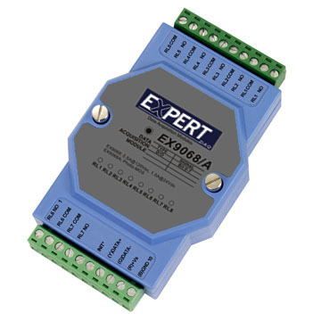
EX9068AD
8*Photo-Mos Relay output LED
127,00 EUR
inkl. Umsatzsteuer 151,13 EUR
- 8 Isolated PhotoMOS Relay Outputs:
Each channel provides a normally open (Form A) PhotoMOS relay output capable of switching up to 350 VAC (peak) or 0.13 A (peak). The outputs are fully isolated and designed for low‑level analog signal control without distortion.
- High‑Speed Switching:
Typical turn‑on time of 0.7 ms and turn‑off time of 0.05 ms enable rapid response suitable for high‑speed inspection systems and communication equipment.
- High Isolation Voltage:
5000 VAC channel‑to‑system isolation ensures robust protection against electrical noise and transient surges.
- Low Output Resistance and Capacitance:
Output resistance of 23 Ω and I/O capacitance of 0.8 pF (at 1 MHz) minimize signal distortion and crosstalk, making the module ideal for precision analog signal routing.
- Wide Power Supply Range:
Operates from +10 VDC to +30 VDC, allowing flexible integration into various control systems.
- Low Power Consumption:
Typical power consumption is only 1.4 W, supporting energy‑efficient operation.
- Status Indication:
Eight front‑panel LEDs provide real‑time output channel status indication.
- Dual Watchdog System:
Hardware (module) and software (host) watchdogs ensure reliable operation and automatic recovery from communication or system faults.
- EEPROM Configuration Storage:
Retains module address, baud rate, and configuration parameters even after power loss.
- INIT* Mode for Configuration Recovery:
A dedicated INIT* pin or switch allows resetting communication parameters to default values for troubleshooting or reconfiguration.
- Modbus RTU and ASCII Command Support:
Fully compatible with Modbus RTU protocol for PLC and SCADA integration, and ASCII command mode for direct serial control.
- Compact, DIN‑rail Mountable Design:
Designed for industrial environments with wide operating temperature range and robust mechanical construction.
Each channel provides a normally open (Form A) PhotoMOS relay output capable of switching up to 350 VAC (peak) or 0.13 A (peak). The outputs are fully isolated and designed for low‑level analog signal control without distortion.
- High‑Speed Switching:
Typical turn‑on time of 0.7 ms and turn‑off time of 0.05 ms enable rapid response suitable for high‑speed inspection systems and communication equipment.
- High Isolation Voltage:
5000 VAC channel‑to‑system isolation ensures robust protection against electrical noise and transient surges.
- Low Output Resistance and Capacitance:
Output resistance of 23 Ω and I/O capacitance of 0.8 pF (at 1 MHz) minimize signal distortion and crosstalk, making the module ideal for precision analog signal routing.
- Wide Power Supply Range:
Operates from +10 VDC to +30 VDC, allowing flexible integration into various control systems.
- Low Power Consumption:
Typical power consumption is only 1.4 W, supporting energy‑efficient operation.
- Status Indication:
Eight front‑panel LEDs provide real‑time output channel status indication.
- Dual Watchdog System:
Hardware (module) and software (host) watchdogs ensure reliable operation and automatic recovery from communication or system faults.
- EEPROM Configuration Storage:
Retains module address, baud rate, and configuration parameters even after power loss.
- INIT* Mode for Configuration Recovery:
A dedicated INIT* pin or switch allows resetting communication parameters to default values for troubleshooting or reconfiguration.
- Modbus RTU and ASCII Command Support:
Fully compatible with Modbus RTU protocol for PLC and SCADA integration, and ASCII command mode for direct serial control.
- Compact, DIN‑rail Mountable Design:
Designed for industrial environments with wide operating temperature range and robust mechanical construction.
Comprehensive Product Summary – EX9068AD / EX9068AD‑M
### 1. Product Overview
Product Name: EX9068AD
Model: EX9068AD‑M
Series: EX9000 Series – Digital Output Modules
Article Number: EX9068AD
Manufacturer: EX Industrial Automation (part of the EX9000 modular I/O family)
The EX9068AD‑M is an 8‑channel isolated PhotoMOS relay output module designed for high‑speed, low‑distortion switching of analog and digital signals. It communicates via a 2‑wire RS‑485 interface and supports both ASCII and Modbus RTU protocols. The module is part of the EX9000 distributed I/O system, which provides flexible, isolated digital and analog I/O expansion for industrial automation, data acquisition, and remote control applications.
### 2. Key Features
- 8 Isolated PhotoMOS Relay Outputs:
Each channel provides a normally open (Form A) PhotoMOS relay output capable of switching up to 350 VAC (peak) or 0.13 A (peak). The outputs are fully isolated and designed for low‑level analog signal control without distortion.
- High‑Speed Switching:
Typical turn‑on time of 0.7 ms and turn‑off time of 0.05 ms enable rapid response suitable for high‑speed inspection systems and communication equipment.
- High Isolation Voltage:
5000 VAC channel‑to‑system isolation ensures robust protection against electrical noise and transient surges.
- Low Output Resistance and Capacitance:
Output resistance of 23 Ω and I/O capacitance of 0.8 pF (at 1 MHz) minimize signal distortion and crosstalk, making the module ideal for precision analog signal routing.
- Wide Power Supply Range:
Operates from +10 VDC to +30 VDC, allowing flexible integration into various control systems.
- Low Power Consumption:
Typical power consumption is only 1.4 W, supporting energy‑efficient operation.
- Status Indication:
Eight front‑panel LEDs provide real‑time output channel status indication.
- Dual Watchdog System:
Hardware (module) and software (host) watchdogs ensure reliable operation and automatic recovery from communication or system faults.
- EEPROM Configuration Storage:
Retains module address, baud rate, and configuration parameters even after power loss.
- INIT* Mode for Configuration Recovery:
A dedicated INIT* pin or switch allows resetting communication parameters to default values for troubleshooting or reconfiguration.
- Modbus RTU and ASCII Command Support:
Fully compatible with Modbus RTU protocol for PLC and SCADA integration, and ASCII command mode for direct serial control.
- Compact, DIN‑rail Mountable Design:
Designed for industrial environments with wide operating temperature range and robust mechanical construction.
### 3. Technical Specifications
| Parameter | Specification |
|----------------|------------------|
| Interface | RS‑485, 2‑wire |
| Communication Speeds | 1200, 2400, 4800, 9600, 19.2 K, 38.4 K, 57.6 K, 115.2 K bps |
| Output Channels | 8 isolated PhotoMOS relay outputs (Form A, normally open) |
| Output Rating | 0 – 350 VAC max (peak), 0 – 0.13 A max (peak) |
| Turn‑On Time | 0.7 ms (typical) |
| Turn‑Off Time | 0.05 ms (typical) |
| Output Resistance | 23 Ω |
| I/O Capacitance | 0.8 pF (f = 1 MHz) |
| Isolation Voltage | 5000 VAC channel‑to‑system |
| Power Supply | +10 VDC to +30 VDC |
| Power Consumption | 1.4 W (typical) |
| Status Indicators | 8 × LEDs (one per output channel) |
| Operating Temperature | −25 °C to +75 °C |
| Storage Temperature | −30 °C to +75 °C |
| Minimum Mechanical Life | 10⁵ operations |
| Surge Strength | 1500 V |
| Mounting | DIN‑rail or panel mount |
| Protocol Support | Modbus RTU (default), ASCII command mode |
| Default Address | 01 |
| Default Baud Rate | 9600 bps |
| Default DIO Type | 40 (Digital Output Module) |
### 4. Functionality
The EX9068AD‑M functions as an 8‑channel digital output module using PhotoMOS solid‑state relays. Each channel operates independently, providing electrically isolated switching for AC or DC loads. The module is controlled via RS‑485 serial communication, allowing integration into distributed control networks.
Operation Modes:
- Normal Mode: Standard operation using Modbus RTU or ASCII commands.
- INIT* Mode: Configuration recovery mode activated by grounding the INIT* pin or sliding the INIT* switch to the ON position. Used to reset communication parameters (address = 00, baud = 9600 bps, checksum = disabled).
Use Cases:
- High‑speed inspection and test systems requiring rapid, low‑distortion signal switching.
- Telecommunication and data communication equipment control.
- Industrial automation systems for signal routing, relay control, and process actuation.
- Remote I/O expansion for PLCs and SCADA systems.
Compatibility:
- Fully compatible with EX9000 series command set and Modbus RTU protocol.
- Works with standard Modbus masters, PLCs, and PC‑based SCADA software.
- Can be configured using EX9000 utility software or ASCII command interface.
### 5. Components & Accessories
Included Components:
- EX9068AD‑M module unit
- Terminal block connectors for power and signal wiring
- Integrated status LEDs (8 × output indicators)
- Built‑in RS‑485 communication port
- INIT* configuration pin (or switch on rear panel)
Optional Accessories:
- RS‑485 to USB or RS‑232 converters for PC connection
- DIN‑rail mounting brackets
- External power supply (10–30 VDC)
- Communication cables and terminal adapters
Connectors:
- Power Input: +10 V to +30 V DC terminal
- RS‑485 Interface: 2‑wire differential (Data +, Data –)
- Relay Outputs: 8 × channel terminals (NO contacts, individually isolated)
### 6. Installation & Setup
Power Requirements:
Supply voltage between +10 VDC and +30 VDC. Ensure stable, regulated DC power for reliable operation.
Mounting Options:
DIN‑rail or panel mounting. Maintain adequate spacing for ventilation and wiring access.
Wiring:
- Connect RS‑485 Data + and Data – lines to the network bus.
- Connect each output channel to the controlled load (normally open contact).
- Observe polarity and isolation requirements.
Configuration:
- Default settings: Address = 01, Baud = 9600 bps, Protocol = Modbus RTU.
- Configuration can be changed via ASCII commands or Modbus registers.
- To reset configuration, activate INIT* mode by grounding the INIT* pin or using the rear switch.
Jumper Setting (EX9068A/M only):
- JP1 Function: Selects pin 6 usage.
- *INIT* (default): Enables configuration mode access.
- *RL8 COM:* Assigns pin 6 as common terminal for relay 8.
INIT* Mode Activation Steps:
1. Power off the module.
2. Connect INIT* pin to GND (or slide INIT* switch to ON).
3. Power on the module.
4. Send `$002` command at 9600 bps to read configuration.
5. Modify parameters as needed, then disconnect INIT* or return switch to Normal position.
6. Power cycle to apply new settings.
### 7. Performance & Capabilities
Switching Performance:
- Turn‑on time: 0.7 ms typical
- Turn‑off time: 0.05 ms typical
- Suitable for high‑speed control applications.
Load Capacity:
- 0 – 350 VAC max (peak) or 0 – 0.13 A max (peak) per channel.
- Designed for low‑power signal switching rather than high‑current loads.
Isolation & Protection:
- 5000 VAC isolation between channels and system bus.
- 1500 V surge strength for transient protection.
- Dual watchdog system ensures safe fallback to predefined “Safe Value” on communication loss.
Reliability:
- Minimum mechanical life of 10⁵ operations.
- EEPROM retains configuration and safe/power‑on values.
- Host and module watchdogs prevent uncontrolled outputs.
Limitations:
- Not intended for high‑current or inductive load switching.
- Maximum load current limited to 0.13 A peak per channel.
- Requires proper grounding and shielding for optimal RS‑485 communication.
### 8. Standards & Compliance
- Communication Protocols:
- Modbus RTU (default)
- ASCII command mode (for configuration and diagnostics)
- Electrical Isolation:
- 5000 VAC isolation voltage
- 1500 V surge strength
- Environmental Ratings:
- Operating temperature: −25 °C to +75 °C
- Storage temperature: −30 °C to +75 °C
- Safety & Reliability Features:
- Dual watchdog (hardware + software)
- EEPROM configuration retention
- Safe Value and Power‑On Value storage
- Host watchdog timeout protection
- Industry Standards:
- RS‑485 serial communication standard
- Modbus RTU protocol compliance
- Designed for industrial automation and data acquisition environments
### 9. Additional Information
Warranty:
Standard manufacturer warranty (typically one year) covering defects in materials and workmanship under normal operating conditions.
Technical Support:
Comprehensive documentation, configuration utilities, and firmware updates available through the manufacturer’s support portal.
Support includes Modbus register maps, ASCII command reference, and wiring diagrams.
Maintenance:
- Periodic inspection of wiring and terminal connections recommended.
- Ensure clean, dry environment to maintain insulation integrity.
- Firmware updates can be applied via RS‑485 interface when available.
Firmware & Updates:
- Firmware version readable via `$AAF` command (e.g., version D03.11).
- Updates may include protocol enhancements or performance improvements.
Default Communication Parameters:
- Address: 01
- Baud Rate: 9600 bps
- Data Format: 8 N 1 (no parity, 1 stop bit)
- Protocol: Modbus RTU
- DIO Type: 40 (Digital Output Module)
Modbus Mapping Summary:
- DO Channels: 00001 – 00008 (R/W)
- Safe Values: 00129 – 00136 (R/W)
- Power‑On Values: 00161 – 00168 (R/W)
- WDT Timeout Value: 40489 (R/W, 0–255 × 0.1 s)
- WDT Enable/Disable: 00261 (R/W)
- WDT Timeout Status: 00270 (R/W, write 0xFF00 to clear)
- Module Name: 40483 – 40484 (R)
- Module Address: 40485 (R/W)
- Baud Rate: 40486 (R/W)
Command Interface Examples:
- `@AA(Data)` – Set digital output value.
- `$AA6` – Read digital output status.
- `~AA5V` – Set Power‑On or Safe Value.
- `$AAF` – Read firmware version.
- `$AAM` – Read module name.
- `~AA3EVV` – Set host watchdog timeout value.
Safety Operation Modes:
- Power‑On Value: Output state applied after reset or power‑up.
- Safe Value: Output state applied when host watchdog timeout occurs.
- Output Command Value: Active output state when communication is normal.
Dual Watchdog Function:
- Module Watchdog: Hardware circuit monitoring internal operation; resets module if malfunction detected.
- Host Watchdog: Software timer monitoring communication; if timeout occurs, outputs revert to Safe Value.
Reset & Status Monitoring:
- `$AA5` – Read reset status (1 = reset occurred).
- `~AA0` – Read module status (00 = normal, 04 = timeout).
- `~AA1` – Reset module status.
Environmental & Mechanical Considerations:
- Designed for industrial environments with wide temperature tolerance.
- Compact form factor suitable for control cabinets and distributed I/O panels.
- Requires proper RS‑485 bus termination and biasing for stable communication.
### Summary
The EX9068AD‑M is a high‑performance, 8‑channel PhotoMOS relay output module engineered for precision signal control in industrial and communication systems. Its combination of high isolation, fast switching, and Modbus RTU compatibility makes it ideal for applications requiring reliable, low‑distortion switching of analog or digital signals. With robust watchdog protection, EEPROM configuration storage, and flexible communication options, the EX9068AD‑M delivers dependable operation in demanding automation environments.
### 1. Product Overview
Product Name: EX9068AD
Model: EX9068AD‑M
Series: EX9000 Series – Digital Output Modules
Article Number: EX9068AD
Manufacturer: EX Industrial Automation (part of the EX9000 modular I/O family)
The EX9068AD‑M is an 8‑channel isolated PhotoMOS relay output module designed for high‑speed, low‑distortion switching of analog and digital signals. It communicates via a 2‑wire RS‑485 interface and supports both ASCII and Modbus RTU protocols. The module is part of the EX9000 distributed I/O system, which provides flexible, isolated digital and analog I/O expansion for industrial automation, data acquisition, and remote control applications.
### 2. Key Features
- 8 Isolated PhotoMOS Relay Outputs:
Each channel provides a normally open (Form A) PhotoMOS relay output capable of switching up to 350 VAC (peak) or 0.13 A (peak). The outputs are fully isolated and designed for low‑level analog signal control without distortion.
- High‑Speed Switching:
Typical turn‑on time of 0.7 ms and turn‑off time of 0.05 ms enable rapid response suitable for high‑speed inspection systems and communication equipment.
- High Isolation Voltage:
5000 VAC channel‑to‑system isolation ensures robust protection against electrical noise and transient surges.
- Low Output Resistance and Capacitance:
Output resistance of 23 Ω and I/O capacitance of 0.8 pF (at 1 MHz) minimize signal distortion and crosstalk, making the module ideal for precision analog signal routing.
- Wide Power Supply Range:
Operates from +10 VDC to +30 VDC, allowing flexible integration into various control systems.
- Low Power Consumption:
Typical power consumption is only 1.4 W, supporting energy‑efficient operation.
- Status Indication:
Eight front‑panel LEDs provide real‑time output channel status indication.
- Dual Watchdog System:
Hardware (module) and software (host) watchdogs ensure reliable operation and automatic recovery from communication or system faults.
- EEPROM Configuration Storage:
Retains module address, baud rate, and configuration parameters even after power loss.
- INIT* Mode for Configuration Recovery:
A dedicated INIT* pin or switch allows resetting communication parameters to default values for troubleshooting or reconfiguration.
- Modbus RTU and ASCII Command Support:
Fully compatible with Modbus RTU protocol for PLC and SCADA integration, and ASCII command mode for direct serial control.
- Compact, DIN‑rail Mountable Design:
Designed for industrial environments with wide operating temperature range and robust mechanical construction.
### 3. Technical Specifications
| Parameter | Specification |
|----------------|------------------|
| Interface | RS‑485, 2‑wire |
| Communication Speeds | 1200, 2400, 4800, 9600, 19.2 K, 38.4 K, 57.6 K, 115.2 K bps |
| Output Channels | 8 isolated PhotoMOS relay outputs (Form A, normally open) |
| Output Rating | 0 – 350 VAC max (peak), 0 – 0.13 A max (peak) |
| Turn‑On Time | 0.7 ms (typical) |
| Turn‑Off Time | 0.05 ms (typical) |
| Output Resistance | 23 Ω |
| I/O Capacitance | 0.8 pF (f = 1 MHz) |
| Isolation Voltage | 5000 VAC channel‑to‑system |
| Power Supply | +10 VDC to +30 VDC |
| Power Consumption | 1.4 W (typical) |
| Status Indicators | 8 × LEDs (one per output channel) |
| Operating Temperature | −25 °C to +75 °C |
| Storage Temperature | −30 °C to +75 °C |
| Minimum Mechanical Life | 10⁵ operations |
| Surge Strength | 1500 V |
| Mounting | DIN‑rail or panel mount |
| Protocol Support | Modbus RTU (default), ASCII command mode |
| Default Address | 01 |
| Default Baud Rate | 9600 bps |
| Default DIO Type | 40 (Digital Output Module) |
### 4. Functionality
The EX9068AD‑M functions as an 8‑channel digital output module using PhotoMOS solid‑state relays. Each channel operates independently, providing electrically isolated switching for AC or DC loads. The module is controlled via RS‑485 serial communication, allowing integration into distributed control networks.
Operation Modes:
- Normal Mode: Standard operation using Modbus RTU or ASCII commands.
- INIT* Mode: Configuration recovery mode activated by grounding the INIT* pin or sliding the INIT* switch to the ON position. Used to reset communication parameters (address = 00, baud = 9600 bps, checksum = disabled).
Use Cases:
- High‑speed inspection and test systems requiring rapid, low‑distortion signal switching.
- Telecommunication and data communication equipment control.
- Industrial automation systems for signal routing, relay control, and process actuation.
- Remote I/O expansion for PLCs and SCADA systems.
Compatibility:
- Fully compatible with EX9000 series command set and Modbus RTU protocol.
- Works with standard Modbus masters, PLCs, and PC‑based SCADA software.
- Can be configured using EX9000 utility software or ASCII command interface.
### 5. Components & Accessories
Included Components:
- EX9068AD‑M module unit
- Terminal block connectors for power and signal wiring
- Integrated status LEDs (8 × output indicators)
- Built‑in RS‑485 communication port
- INIT* configuration pin (or switch on rear panel)
Optional Accessories:
- RS‑485 to USB or RS‑232 converters for PC connection
- DIN‑rail mounting brackets
- External power supply (10–30 VDC)
- Communication cables and terminal adapters
Connectors:
- Power Input: +10 V to +30 V DC terminal
- RS‑485 Interface: 2‑wire differential (Data +, Data –)
- Relay Outputs: 8 × channel terminals (NO contacts, individually isolated)
### 6. Installation & Setup
Power Requirements:
Supply voltage between +10 VDC and +30 VDC. Ensure stable, regulated DC power for reliable operation.
Mounting Options:
DIN‑rail or panel mounting. Maintain adequate spacing for ventilation and wiring access.
Wiring:
- Connect RS‑485 Data + and Data – lines to the network bus.
- Connect each output channel to the controlled load (normally open contact).
- Observe polarity and isolation requirements.
Configuration:
- Default settings: Address = 01, Baud = 9600 bps, Protocol = Modbus RTU.
- Configuration can be changed via ASCII commands or Modbus registers.
- To reset configuration, activate INIT* mode by grounding the INIT* pin or using the rear switch.
Jumper Setting (EX9068A/M only):
- JP1 Function: Selects pin 6 usage.
- *INIT* (default): Enables configuration mode access.
- *RL8 COM:* Assigns pin 6 as common terminal for relay 8.
INIT* Mode Activation Steps:
1. Power off the module.
2. Connect INIT* pin to GND (or slide INIT* switch to ON).
3. Power on the module.
4. Send `$002` command at 9600 bps to read configuration.
5. Modify parameters as needed, then disconnect INIT* or return switch to Normal position.
6. Power cycle to apply new settings.
### 7. Performance & Capabilities
Switching Performance:
- Turn‑on time: 0.7 ms typical
- Turn‑off time: 0.05 ms typical
- Suitable for high‑speed control applications.
Load Capacity:
- 0 – 350 VAC max (peak) or 0 – 0.13 A max (peak) per channel.
- Designed for low‑power signal switching rather than high‑current loads.
Isolation & Protection:
- 5000 VAC isolation between channels and system bus.
- 1500 V surge strength for transient protection.
- Dual watchdog system ensures safe fallback to predefined “Safe Value” on communication loss.
Reliability:
- Minimum mechanical life of 10⁵ operations.
- EEPROM retains configuration and safe/power‑on values.
- Host and module watchdogs prevent uncontrolled outputs.
Limitations:
- Not intended for high‑current or inductive load switching.
- Maximum load current limited to 0.13 A peak per channel.
- Requires proper grounding and shielding for optimal RS‑485 communication.
### 8. Standards & Compliance
- Communication Protocols:
- Modbus RTU (default)
- ASCII command mode (for configuration and diagnostics)
- Electrical Isolation:
- 5000 VAC isolation voltage
- 1500 V surge strength
- Environmental Ratings:
- Operating temperature: −25 °C to +75 °C
- Storage temperature: −30 °C to +75 °C
- Safety & Reliability Features:
- Dual watchdog (hardware + software)
- EEPROM configuration retention
- Safe Value and Power‑On Value storage
- Host watchdog timeout protection
- Industry Standards:
- RS‑485 serial communication standard
- Modbus RTU protocol compliance
- Designed for industrial automation and data acquisition environments
### 9. Additional Information
Warranty:
Standard manufacturer warranty (typically one year) covering defects in materials and workmanship under normal operating conditions.
Technical Support:
Comprehensive documentation, configuration utilities, and firmware updates available through the manufacturer’s support portal.
Support includes Modbus register maps, ASCII command reference, and wiring diagrams.
Maintenance:
- Periodic inspection of wiring and terminal connections recommended.
- Ensure clean, dry environment to maintain insulation integrity.
- Firmware updates can be applied via RS‑485 interface when available.
Firmware & Updates:
- Firmware version readable via `$AAF` command (e.g., version D03.11).
- Updates may include protocol enhancements or performance improvements.
Default Communication Parameters:
- Address: 01
- Baud Rate: 9600 bps
- Data Format: 8 N 1 (no parity, 1 stop bit)
- Protocol: Modbus RTU
- DIO Type: 40 (Digital Output Module)
Modbus Mapping Summary:
- DO Channels: 00001 – 00008 (R/W)
- Safe Values: 00129 – 00136 (R/W)
- Power‑On Values: 00161 – 00168 (R/W)
- WDT Timeout Value: 40489 (R/W, 0–255 × 0.1 s)
- WDT Enable/Disable: 00261 (R/W)
- WDT Timeout Status: 00270 (R/W, write 0xFF00 to clear)
- Module Name: 40483 – 40484 (R)
- Module Address: 40485 (R/W)
- Baud Rate: 40486 (R/W)
Command Interface Examples:
- `@AA(Data)` – Set digital output value.
- `$AA6` – Read digital output status.
- `~AA5V` – Set Power‑On or Safe Value.
- `$AAF` – Read firmware version.
- `$AAM` – Read module name.
- `~AA3EVV` – Set host watchdog timeout value.
Safety Operation Modes:
- Power‑On Value: Output state applied after reset or power‑up.
- Safe Value: Output state applied when host watchdog timeout occurs.
- Output Command Value: Active output state when communication is normal.
Dual Watchdog Function:
- Module Watchdog: Hardware circuit monitoring internal operation; resets module if malfunction detected.
- Host Watchdog: Software timer monitoring communication; if timeout occurs, outputs revert to Safe Value.
Reset & Status Monitoring:
- `$AA5` – Read reset status (1 = reset occurred).
- `~AA0` – Read module status (00 = normal, 04 = timeout).
- `~AA1` – Reset module status.
Environmental & Mechanical Considerations:
- Designed for industrial environments with wide temperature tolerance.
- Compact form factor suitable for control cabinets and distributed I/O panels.
- Requires proper RS‑485 bus termination and biasing for stable communication.
### Summary
The EX9068AD‑M is a high‑performance, 8‑channel PhotoMOS relay output module engineered for precision signal control in industrial and communication systems. Its combination of high isolation, fast switching, and Modbus RTU compatibility makes it ideal for applications requiring reliable, low‑distortion switching of analog or digital signals. With robust watchdog protection, EEPROM configuration storage, and flexible communication options, the EX9068AD‑M delivers dependable operation in demanding automation environments.


Kein Zubehör vorhanden.