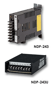
NDP-243
SUCHEN SIE DIE PASSENDE
INDUSTRIELLE LÖSUNG?
Entdecken Sie Embedded-, Kommunikations- und Automatisierungslösungen für Ihre Anwendung.
The NuDAM‑6012 is a multi‑function, high‑gain analog input module designed for industrial data acquisition and remote monitoring applications. It provides a single differential analog input channel with programmable voltage ranges and integrated digital I/O for alarm and control functions. The module communicates via a two‑wire RS‑485 interface, supporting multi‑drop networking and long‑distance communication.
Primary Features:
- 1 differential analog input channel with programmable voltage range.
- High‑gain measurement capability for low‑level signals (±150 mV to ±10 V).
- 16‑bit resolution analog‑to‑digital conversion for precise measurement.
- RS‑485 communication interface (2‑wire, half‑duplex) with baud rates up to 115.2 kbps.
- 5000 Vrms isolation between analog and communication circuits (2500 Vrms for ND‑6012/D).
- 2 open‑collector digital outputs (50 mA sink current each) for alarms or control.
- 1 digital input channel configurable as a general input or event counter (up to 50 Hz).
- Programmable high/low alarm thresholds with latch or momentary modes.
- Host and internal watchdog timers for system reliability and fail‑safe operation.
- LED display (5½‑digit) on the “D” version for real‑time value indication.
- Software‑configurable parameters including address, baud rate, input range, and data format.
- Compact, DIN‑rail mountable design for distributed I/O networks.
- Power supply range: +10 V DC to +30 V DC.
Primary Features:
- 1 differential analog input channel with programmable voltage range.
- High‑gain measurement capability for low‑level signals (±150 mV to ±10 V).
- 16‑bit resolution analog‑to‑digital conversion for precise measurement.
- RS‑485 communication interface (2‑wire, half‑duplex) with baud rates up to 115.2 kbps.
- 5000 Vrms isolation between analog and communication circuits (2500 Vrms for ND‑6012/D).
- 2 open‑collector digital outputs (50 mA sink current each) for alarms or control.
- 1 digital input channel configurable as a general input or event counter (up to 50 Hz).
- Programmable high/low alarm thresholds with latch or momentary modes.
- Host and internal watchdog timers for system reliability and fail‑safe operation.
- LED display (5½‑digit) on the “D” version for real‑time value indication.
- Software‑configurable parameters including address, baud rate, input range, and data format.
- Compact, DIN‑rail mountable design for distributed I/O networks.
- Power supply range: +10 V DC to +30 V DC.
Comprehensive Product Summary: ADLINK NuDAM ND‑6012 High‑Gain Analog Input Module
### 1. Product Overview
Product Name: NuDAM High‑Gain Analog Input Module
Model: ND‑6012 / NuDAM‑6012 / NuDAM‑6012D
Series: NuDAM 601X Analog Input Module Series
Article Number: ND‑6012 (ADLINK Part No. 91‑21002‑001)
Manufacturer: ADLINK Technology Inc.
Country of Origin: Taiwan, R.O.C.
Manufacturer Address: 9F, No.166 Jian Yi Road, Chungho City, Taipei 235, Taiwan
Website: [www.adlinktech.com](http://www.adlinktech.com)
Support Email: nudam@adlink.com.tw
Telephone: +886‑2‑8226‑5877
Fax: +886‑2‑8226‑5717
Product Lifecycle:
End‑of‑Life (EOL) Notification No. 20020925‑003, published September 25, 2002.
Suggested Replacement: None (limited stock available at time of EOL).
### 2. Key Features
The NuDAM‑6012 is a multi‑function, high‑gain analog input module designed for industrial data acquisition and remote monitoring applications. It provides a single differential analog input channel with programmable voltage ranges and integrated digital I/O for alarm and control functions. The module communicates via a two‑wire RS‑485 interface, supporting multi‑drop networking and long‑distance communication.
Primary Features:
- 1 differential analog input channel with programmable voltage range.
- High‑gain measurement capability for low‑level signals (±150 mV to ±10 V).
- 16‑bit resolution analog‑to‑digital conversion for precise measurement.
- RS‑485 communication interface (2‑wire, half‑duplex) with baud rates up to 115.2 kbps.
- 5000 Vrms isolation between analog and communication circuits (2500 Vrms for ND‑6012/D).
- 2 open‑collector digital outputs (50 mA sink current each) for alarms or control.
- 1 digital input channel configurable as a general input or event counter (up to 50 Hz).
- Programmable high/low alarm thresholds with latch or momentary modes.
- Host and internal watchdog timers for system reliability and fail‑safe operation.
- LED display (5½‑digit) on the “D” version for real‑time value indication.
- Software‑configurable parameters including address, baud rate, input range, and data format.
- Compact, DIN‑rail mountable design for distributed I/O networks.
- Power supply range: +10 V DC to +30 V DC.
### 3. Technical Specifications
Interface:
- Communication: RS‑485, 2‑wire half‑duplex
- Baud Rates: 1200, 2400, 4800, 9600, 19.2 k, 38.4 k, 115.2 k bps (firmware ≥ A4.00)
- Protocol: ASCII‑based command/response set
- Isolation: 5000 Vrms (standard), 2500 Vrms (ND‑6012/D)
Analog Input:
- Channels: 1 (differential)
- Input Type: Differential voltage or current (via external resistor)
- Resolution: 16 bits
- Input Ranges (programmable):
±10 V, ±5 V, ±1 V, ±500 mV, ±150 mV
- Current Measurement: ±20 mA (requires external 125 Ω precision resistor)
- Accuracy: ±0.05 % of full‑scale range
- Input Impedance: > 100 MΩ (typical)
- Sampling Rate: 10 Hz (nominal)
- Bandwidth: 4 Hz (typical)
Digital I/O:
- Digital Input:
- Channels: 1
- Logic “0”: ≤ +1 V
- Logic “1”: +2 V – +30 V
- Pull‑up Resistor: 10 kΩ
- Max Input Current: 0.5 mA
- Function: General input or event counter (max 50 Hz)
- Digital Output:
- Channels: 2 (open‑collector NPN transistor)
- Max Sink Current: 50 mA per channel
- Max Dissipation: 300 mW
- Max Output Voltage: 30 V DC
- Function: Alarm output or general control
Watchdog Timers:
- Internal Device Watchdog: 150 ms
- Host Programmable Watchdog: 100 ms – 25.5 s
- Power‑Fail Threshold: 4.65 V
- Safety Output State: User‑defined digital output pattern
Power Requirements:
- Supply Voltage: +10 V DC – +30 V DC
- Power Consumption: 1.1 W (standard), 2.0 W (ND‑6012/D)
Environmental:
- Operating Temperature: 0 °C – +60 °C
- Storage Temperature: –20 °C – +80 °C
- Humidity: 0 – 95 % RH, non‑condensing
- Isolation: 2500 – 5000 Vrms (model dependent)
Physical:
- Mounting: DIN‑rail or panel mount
- Enclosure: Industrial‑grade plastic housing
- Dimensions: Approx. 72 mm × 118 mm × 25 mm (typical NuDAM form factor)
- Weight: ~200 g
### 4. Functionality
The ND‑6012 converts analog voltage or current signals into digital data for transmission over an RS‑485 network. It is designed for distributed data acquisition systems where multiple modules communicate with a host controller or PC.
Operating Principle:
1. The analog input signal is applied to the differential input terminals (IN+ / IN–).
2. The signal is conditioned and digitized by a 16‑bit ADC.
3. The microprocessor formats the data according to the selected output mode (engineering units, %FSR, or hexadecimal).
4. The processed data is transmitted via RS‑485 to the host system.
5. Digital outputs can be triggered by alarm thresholds or host commands.
6. The digital input can serve as a counter or event trigger.
Typical Applications:
- Industrial process monitoring and control
- Remote analog signal acquisition
- Sensor and transducer interfacing (voltage/current output)
- Laboratory instrumentation
- SCADA and distributed control systems
- Alarm and event monitoring with digital I/O feedback
Compatibility:
- Fully compatible with other NuDAM 6000‑series modules (6011, 6013, 6014D, 6017, 6018).
- Operates with ADLINK’s NuDAM Administration software and standard RS‑485 converters (e.g., NuDAM‑6520).
- Supports integration with PLCs, PCs, and embedded controllers using ASCII command protocol.
### 5. Components & Accessories
Included Components:
- ND‑6012 or ND‑6012D module
- Terminal block connectors for signal and power wiring
- User documentation (electronic or printed manual)
Optional Accessories:
- RS‑232/RS‑485 converter (NuDAM‑6520)
- External 125 Ω precision resistor for current measurement
- DIN‑rail mounting kit
- Power supply (10–30 V DC regulated)
- Communication cables and termination resistors
Connectors & Pin Assignments:
| Pin | Signal | Description |
|-----|---------|-------------|
| 1 | IN+ | Analog input positive terminal |
| 2 | IN– | Analog input negative terminal |
| 3 | DO1 / HI | Digital output 1 or high alarm output |
| 4 | DI0 / EV | Digital input or event counter |
| 5 | DO0 / LO | Digital output 0 or low alarm output |
| 6 | DEFAULT* | Default configuration pin (short to GND for setup) |
| 7 | DATA+ (Y) | RS‑485 data positive |
| 8 | DATA– (G) | RS‑485 data negative |
| 9 | +Vs (R) | Power input +10 V – +30 V DC |
| 10 | GND (B) | Power ground |
### 6. Installation & Setup
Requirements:
- Host computer with RS‑232 or USB port
- RS‑232/RS‑485 converter (e.g., NuDAM‑6520)
- Power supply (10–30 V DC)
- NuDAM Administration software
Initialization Procedure:
1. Connect the module to the RS‑485 network.
2. Short the DEFAULT* pin to GND and power on to enter default mode.
3. Default parameters:
- Address ID = 00
- Baud rate = 9600 bps
- Checksum = disabled
- Watchdog = disabled
4. Use the configuration utility or ASCII commands to assign a unique address and desired baud rate.
5. Remove the DEFAULT* short and power cycle to apply settings.
Mounting Options:
- DIN‑rail or panel mounting using standard brackets.
- Ensure adequate ventilation and isolation from high‑voltage sources.
Wiring Examples:
- Differential Voltage Input: Connect signal source to IN+ and IN–.
- Current Measurement: Connect through external 125 Ω resistor.
- Digital Input: TTL or open‑collector signal to DI0.
- Digital Output: Connect relay, LED, or SSR load between DOx and external +Vs.
### 7. Performance & Capabilities
Measurement Performance:
- Resolution: 16 bits (1 part in 65,536)
- Accuracy: ±0.05 % FSR
- Sampling Rate: 10 samples/sec
- Bandwidth: 4 Hz (anti‑alias filtered)
- Input Impedance: > 100 MΩ
- Common‑Mode Rejection: > 100 dB
Digital I/O Performance:
- Input counter frequency: up to 50 Hz
- Output switching: up to 30 V DC, 30 mA continuous
Reliability & Protection:
- 2500–5000 Vrms isolation between analog and communication circuits
- Watchdog timers prevent system lockup
- Power‑fail detection ensures safe output state
- Over‑voltage protection up to ±30 V relative to AGND
Limitations:
- Single analog input channel (not multiplexed)
- No built‑in cold‑junction compensation (unlike ND‑6011)
- Requires external resistor for current measurement
- Limited sampling rate (10 Hz) for slow‑changing signals
### 8. Standards & Compliance
Electrical & Safety:
- Isolation: 2500 Vrms (ND‑6012/D), 5000 Vrms (ND‑6012)
- Power Supply Protection: Reverse polarity and surge protection
- EMC Compliance: Designed for industrial environments (EN 55022/55024 equivalent)
Communication Standards:
- RS‑485 (EIA/TIA‑485‑A) compliant
- ASCII command protocol compatible with ADLINK NuDAM series
Quality & Manufacturing:
- Manufactured under ISO 9001 quality management system
- CE‑compliant design (for applicable models)
### 9. Additional Information
Calibration:
- Factory‑calibrated; field calibration supported via software commands.
- Calibration procedure involves applying known offset and span voltages and executing calibration commands (`$(Addr)1` for offset, `$(Addr)0` for span).
- Recommended calibration interval: 12 months.
Maintenance:
- Periodic inspection of wiring and terminal integrity.
- Keep module free from dust and moisture.
- Avoid exposure to vibration or high‑temperature environments.
Firmware & Software:
- Firmware upgradeable via RS‑485 interface (firmware ≥ A4.00 supports 115.2 kbps).
- Compatible with NuDAM Administration Utility for Windows.
- ASCII command set allows integration with custom software or SCADA systems.
Warranty:
- Standard 1‑year limited warranty from date of shipment.
- Covers defects in materials and workmanship under normal operation.
- Excludes damage due to misuse, modification, or operation beyond specifications.
- Return procedure: prepaid shipment, secure packaging, and proof of purchase required.
Support & Service:
- Technical Support: nudam@adlink.com.tw
- Sales & Service: service@adlink.com.tw
- Web Resources: [www.adlinktech.com](http://www.adlinktech.com)
End‑of‑Life Notice:
- Product ND‑6012 declared EOL on September 25, 2002.
- Reason: component obsolescence and product line update.
- No direct replacement available; limited stock remained at time of notice.
### Summary
The ADLINK NuDAM ND‑6012 is a robust, high‑precision analog input module engineered for distributed data acquisition over RS‑485 networks. With its 16‑bit resolution, programmable input ranges, and integrated digital I/O, it provides a flexible solution for industrial monitoring and control. The module’s isolation, watchdog protection, and software configurability ensure reliable operation in demanding environments. Although discontinued, the ND‑6012 remains a reference design for compact, intelligent analog input modules in industrial automation systems.

### 1. Product Overview
Product Name: NuDAM High‑Gain Analog Input Module
Model: ND‑6012 / NuDAM‑6012 / NuDAM‑6012D
Series: NuDAM 601X Analog Input Module Series
Article Number: ND‑6012 (ADLINK Part No. 91‑21002‑001)
Manufacturer: ADLINK Technology Inc.
Country of Origin: Taiwan, R.O.C.
Manufacturer Address: 9F, No.166 Jian Yi Road, Chungho City, Taipei 235, Taiwan
Website: [www.adlinktech.com](http://www.adlinktech.com)
Support Email: nudam@adlink.com.tw
Telephone: +886‑2‑8226‑5877
Fax: +886‑2‑8226‑5717
Product Lifecycle:
End‑of‑Life (EOL) Notification No. 20020925‑003, published September 25, 2002.
Suggested Replacement: None (limited stock available at time of EOL).
### 2. Key Features
The NuDAM‑6012 is a multi‑function, high‑gain analog input module designed for industrial data acquisition and remote monitoring applications. It provides a single differential analog input channel with programmable voltage ranges and integrated digital I/O for alarm and control functions. The module communicates via a two‑wire RS‑485 interface, supporting multi‑drop networking and long‑distance communication.
Primary Features:
- 1 differential analog input channel with programmable voltage range.
- High‑gain measurement capability for low‑level signals (±150 mV to ±10 V).
- 16‑bit resolution analog‑to‑digital conversion for precise measurement.
- RS‑485 communication interface (2‑wire, half‑duplex) with baud rates up to 115.2 kbps.
- 5000 Vrms isolation between analog and communication circuits (2500 Vrms for ND‑6012/D).
- 2 open‑collector digital outputs (50 mA sink current each) for alarms or control.
- 1 digital input channel configurable as a general input or event counter (up to 50 Hz).
- Programmable high/low alarm thresholds with latch or momentary modes.
- Host and internal watchdog timers for system reliability and fail‑safe operation.
- LED display (5½‑digit) on the “D” version for real‑time value indication.
- Software‑configurable parameters including address, baud rate, input range, and data format.
- Compact, DIN‑rail mountable design for distributed I/O networks.
- Power supply range: +10 V DC to +30 V DC.
### 3. Technical Specifications
Interface:
- Communication: RS‑485, 2‑wire half‑duplex
- Baud Rates: 1200, 2400, 4800, 9600, 19.2 k, 38.4 k, 115.2 k bps (firmware ≥ A4.00)
- Protocol: ASCII‑based command/response set
- Isolation: 5000 Vrms (standard), 2500 Vrms (ND‑6012/D)
Analog Input:
- Channels: 1 (differential)
- Input Type: Differential voltage or current (via external resistor)
- Resolution: 16 bits
- Input Ranges (programmable):
±10 V, ±5 V, ±1 V, ±500 mV, ±150 mV
- Current Measurement: ±20 mA (requires external 125 Ω precision resistor)
- Accuracy: ±0.05 % of full‑scale range
- Input Impedance: > 100 MΩ (typical)
- Sampling Rate: 10 Hz (nominal)
- Bandwidth: 4 Hz (typical)
Digital I/O:
- Digital Input:
- Channels: 1
- Logic “0”: ≤ +1 V
- Logic “1”: +2 V – +30 V
- Pull‑up Resistor: 10 kΩ
- Max Input Current: 0.5 mA
- Function: General input or event counter (max 50 Hz)
- Digital Output:
- Channels: 2 (open‑collector NPN transistor)
- Max Sink Current: 50 mA per channel
- Max Dissipation: 300 mW
- Max Output Voltage: 30 V DC
- Function: Alarm output or general control
Watchdog Timers:
- Internal Device Watchdog: 150 ms
- Host Programmable Watchdog: 100 ms – 25.5 s
- Power‑Fail Threshold: 4.65 V
- Safety Output State: User‑defined digital output pattern
Power Requirements:
- Supply Voltage: +10 V DC – +30 V DC
- Power Consumption: 1.1 W (standard), 2.0 W (ND‑6012/D)
Environmental:
- Operating Temperature: 0 °C – +60 °C
- Storage Temperature: –20 °C – +80 °C
- Humidity: 0 – 95 % RH, non‑condensing
- Isolation: 2500 – 5000 Vrms (model dependent)
Physical:
- Mounting: DIN‑rail or panel mount
- Enclosure: Industrial‑grade plastic housing
- Dimensions: Approx. 72 mm × 118 mm × 25 mm (typical NuDAM form factor)
- Weight: ~200 g
### 4. Functionality
The ND‑6012 converts analog voltage or current signals into digital data for transmission over an RS‑485 network. It is designed for distributed data acquisition systems where multiple modules communicate with a host controller or PC.
Operating Principle:
1. The analog input signal is applied to the differential input terminals (IN+ / IN–).
2. The signal is conditioned and digitized by a 16‑bit ADC.
3. The microprocessor formats the data according to the selected output mode (engineering units, %FSR, or hexadecimal).
4. The processed data is transmitted via RS‑485 to the host system.
5. Digital outputs can be triggered by alarm thresholds or host commands.
6. The digital input can serve as a counter or event trigger.
Typical Applications:
- Industrial process monitoring and control
- Remote analog signal acquisition
- Sensor and transducer interfacing (voltage/current output)
- Laboratory instrumentation
- SCADA and distributed control systems
- Alarm and event monitoring with digital I/O feedback
Compatibility:
- Fully compatible with other NuDAM 6000‑series modules (6011, 6013, 6014D, 6017, 6018).
- Operates with ADLINK’s NuDAM Administration software and standard RS‑485 converters (e.g., NuDAM‑6520).
- Supports integration with PLCs, PCs, and embedded controllers using ASCII command protocol.
### 5. Components & Accessories
Included Components:
- ND‑6012 or ND‑6012D module
- Terminal block connectors for signal and power wiring
- User documentation (electronic or printed manual)
Optional Accessories:
- RS‑232/RS‑485 converter (NuDAM‑6520)
- External 125 Ω precision resistor for current measurement
- DIN‑rail mounting kit
- Power supply (10–30 V DC regulated)
- Communication cables and termination resistors
Connectors & Pin Assignments:
| Pin | Signal | Description |
|-----|---------|-------------|
| 1 | IN+ | Analog input positive terminal |
| 2 | IN– | Analog input negative terminal |
| 3 | DO1 / HI | Digital output 1 or high alarm output |
| 4 | DI0 / EV | Digital input or event counter |
| 5 | DO0 / LO | Digital output 0 or low alarm output |
| 6 | DEFAULT* | Default configuration pin (short to GND for setup) |
| 7 | DATA+ (Y) | RS‑485 data positive |
| 8 | DATA– (G) | RS‑485 data negative |
| 9 | +Vs (R) | Power input +10 V – +30 V DC |
| 10 | GND (B) | Power ground |
### 6. Installation & Setup
Requirements:
- Host computer with RS‑232 or USB port
- RS‑232/RS‑485 converter (e.g., NuDAM‑6520)
- Power supply (10–30 V DC)
- NuDAM Administration software
Initialization Procedure:
1. Connect the module to the RS‑485 network.
2. Short the DEFAULT* pin to GND and power on to enter default mode.
3. Default parameters:
- Address ID = 00
- Baud rate = 9600 bps
- Checksum = disabled
- Watchdog = disabled
4. Use the configuration utility or ASCII commands to assign a unique address and desired baud rate.
5. Remove the DEFAULT* short and power cycle to apply settings.
Mounting Options:
- DIN‑rail or panel mounting using standard brackets.
- Ensure adequate ventilation and isolation from high‑voltage sources.
Wiring Examples:
- Differential Voltage Input: Connect signal source to IN+ and IN–.
- Current Measurement: Connect through external 125 Ω resistor.
- Digital Input: TTL or open‑collector signal to DI0.
- Digital Output: Connect relay, LED, or SSR load between DOx and external +Vs.
### 7. Performance & Capabilities
Measurement Performance:
- Resolution: 16 bits (1 part in 65,536)
- Accuracy: ±0.05 % FSR
- Sampling Rate: 10 samples/sec
- Bandwidth: 4 Hz (anti‑alias filtered)
- Input Impedance: > 100 MΩ
- Common‑Mode Rejection: > 100 dB
Digital I/O Performance:
- Input counter frequency: up to 50 Hz
- Output switching: up to 30 V DC, 30 mA continuous
Reliability & Protection:
- 2500–5000 Vrms isolation between analog and communication circuits
- Watchdog timers prevent system lockup
- Power‑fail detection ensures safe output state
- Over‑voltage protection up to ±30 V relative to AGND
Limitations:
- Single analog input channel (not multiplexed)
- No built‑in cold‑junction compensation (unlike ND‑6011)
- Requires external resistor for current measurement
- Limited sampling rate (10 Hz) for slow‑changing signals
### 8. Standards & Compliance
Electrical & Safety:
- Isolation: 2500 Vrms (ND‑6012/D), 5000 Vrms (ND‑6012)
- Power Supply Protection: Reverse polarity and surge protection
- EMC Compliance: Designed for industrial environments (EN 55022/55024 equivalent)
Communication Standards:
- RS‑485 (EIA/TIA‑485‑A) compliant
- ASCII command protocol compatible with ADLINK NuDAM series
Quality & Manufacturing:
- Manufactured under ISO 9001 quality management system
- CE‑compliant design (for applicable models)
### 9. Additional Information
Calibration:
- Factory‑calibrated; field calibration supported via software commands.
- Calibration procedure involves applying known offset and span voltages and executing calibration commands (`$(Addr)1` for offset, `$(Addr)0` for span).
- Recommended calibration interval: 12 months.
Maintenance:
- Periodic inspection of wiring and terminal integrity.
- Keep module free from dust and moisture.
- Avoid exposure to vibration or high‑temperature environments.
Firmware & Software:
- Firmware upgradeable via RS‑485 interface (firmware ≥ A4.00 supports 115.2 kbps).
- Compatible with NuDAM Administration Utility for Windows.
- ASCII command set allows integration with custom software or SCADA systems.
Warranty:
- Standard 1‑year limited warranty from date of shipment.
- Covers defects in materials and workmanship under normal operation.
- Excludes damage due to misuse, modification, or operation beyond specifications.
- Return procedure: prepaid shipment, secure packaging, and proof of purchase required.
Support & Service:
- Technical Support: nudam@adlink.com.tw
- Sales & Service: service@adlink.com.tw
- Web Resources: [www.adlinktech.com](http://www.adlinktech.com)
End‑of‑Life Notice:
- Product ND‑6012 declared EOL on September 25, 2002.
- Reason: component obsolescence and product line update.
- No direct replacement available; limited stock remained at time of notice.
### Summary
The ADLINK NuDAM ND‑6012 is a robust, high‑precision analog input module engineered for distributed data acquisition over RS‑485 networks. With its 16‑bit resolution, programmable input ranges, and integrated digital I/O, it provides a flexible solution for industrial monitoring and control. The module’s isolation, watchdog protection, and software configurability ensure reliable operation in demanding environments. Although discontinued, the ND‑6012 remains a reference design for compact, intelligent analog input modules in industrial automation systems.
-
ND-6012-EOL.pdf
Manual
-
ND-601X_Manual_1.pdf
Manual
-
ND601X Manual.PDF
Manual