DIN-100S-01
SUCHEN SIE DIE PASSENDE
INDUSTRIELLE LÖSUNG?
Entdecken Sie Embedded-, Kommunikations- und Automatisierungslösungen für Ihre Anwendung.
- 48 TTL-Compatible Digital I/O Channels:
Provides 48 bidirectional digital lines configurable as input or output in 8-bit port groups.
- High Current Drive Capability:
Each output channel can source up to 15 mA and sink up to 48 mA, suitable for driving LEDs, relays, and other TTL/CMOS devices.
- Change-of-State (COS) Interrupt:
Generates an interrupt when any input bit changes state, enabling event-driven digital monitoring.
- Dual Interrupt System:
Two independent interrupt sources (INT1 and INT2) allow simultaneous handling of multiple event types such as COS, timer, or counter events.
- Output Status Readback:
Supports readback of output states for verification and closed-loop control.
- External Trigger Input:
Accepts an external trigger signal (EXTTRG, pin 99) to latch input data synchronously with external events.
- Programmable Timer/Counter:
Includes one 8254 programmable timer/counter chip providing a 32-bit timer and a 16-bit event counter for timing and counting applications.
- User-Configurable Power-On State:
Each port can be configured via jumpers to power up in a pulled-high, pulled-low, or floating state.
- Onboard Power Outputs:
Provides +5 V and +12 V outputs on the SCSI connector (protected by resettable fuses) for powering external circuits.
- Watchdog Timer:
32-bit watchdog timer ensures system reliability and can reset outputs or trigger interrupts on timeout.
- Compact PCI Form Factor:
Half-size PCI card (158 mm × 107 mm) compliant with PCI Bus Rev. 2.1.
Provides 48 bidirectional digital lines configurable as input or output in 8-bit port groups.
- High Current Drive Capability:
Each output channel can source up to 15 mA and sink up to 48 mA, suitable for driving LEDs, relays, and other TTL/CMOS devices.
- Change-of-State (COS) Interrupt:
Generates an interrupt when any input bit changes state, enabling event-driven digital monitoring.
- Dual Interrupt System:
Two independent interrupt sources (INT1 and INT2) allow simultaneous handling of multiple event types such as COS, timer, or counter events.
- Output Status Readback:
Supports readback of output states for verification and closed-loop control.
- External Trigger Input:
Accepts an external trigger signal (EXTTRG, pin 99) to latch input data synchronously with external events.
- Programmable Timer/Counter:
Includes one 8254 programmable timer/counter chip providing a 32-bit timer and a 16-bit event counter for timing and counting applications.
- User-Configurable Power-On State:
Each port can be configured via jumpers to power up in a pulled-high, pulled-low, or floating state.
- Onboard Power Outputs:
Provides +5 V and +12 V outputs on the SCSI connector (protected by resettable fuses) for powering external circuits.
- Watchdog Timer:
32-bit watchdog timer ensures system reliability and can reset outputs or trigger interrupts on timeout.
- Compact PCI Form Factor:
Half-size PCI card (158 mm × 107 mm) compliant with PCI Bus Rev. 2.1.
Comprehensive Product Summary: ADLINK PCI-7348 High-Current 48-Channel Digital I/O Card
### 1. Product Overview
Product Name: PCI-7348
Model: PCI-7348
Series: NuDAQ® PCI DIO Series
Article Number: PCI-7348
Manufacturer: ADLINK Technology Inc.
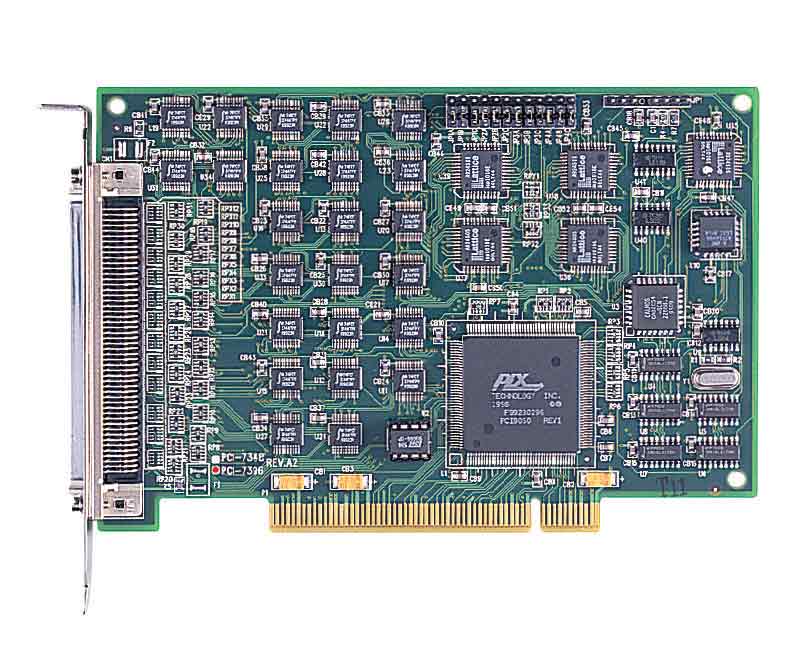
The ADLINK PCI-7348 is a high-current, 48-channel digital input/output (DIO) interface card designed for industrial automation, monitoring, and control applications. It belongs to ADLINK’s NuDAQ® family of PCI-based data acquisition and control products. The PCI-7348 provides robust TTL-compatible digital I/O capabilities with advanced interrupt handling, change-of-state (COS) detection, and output readback functionality. It is engineered for high reliability and performance in demanding industrial environments.
### 2. Key Features
- 48 TTL-Compatible Digital I/O Channels:
Provides 48 bidirectional digital lines configurable as input or output in 8-bit port groups.
- High Current Drive Capability:
Each output channel can source up to 15 mA and sink up to 48 mA, suitable for driving LEDs, relays, and other TTL/CMOS devices.
- Change-of-State (COS) Interrupt:
Generates an interrupt when any input bit changes state, enabling event-driven digital monitoring.
- Dual Interrupt System:
Two independent interrupt sources (INT1 and INT2) allow simultaneous handling of multiple event types such as COS, timer, or counter events.
- Output Status Readback:
Supports readback of output states for verification and closed-loop control.
- External Trigger Input:
Accepts an external trigger signal (EXTTRG, pin 99) to latch input data synchronously with external events.
- Programmable Timer/Counter:
Includes one 8254 programmable timer/counter chip providing a 32-bit timer and a 16-bit event counter for timing and counting applications.
- User-Configurable Power-On State:
Each port can be configured via jumpers to power up in a pulled-high, pulled-low, or floating state.
- Onboard Power Outputs:
Provides +5 V and +12 V outputs on the SCSI connector (protected by resettable fuses) for powering external circuits.
- Watchdog Timer:
32-bit watchdog timer ensures system reliability and can reset outputs or trigger interrupts on timeout.
- Compact PCI Form Factor:
Half-size PCI card (158 mm × 107 mm) compliant with PCI Bus Rev. 2.1.
### 3. Technical Specifications
Digital I/O:
- Number of Channels: 48 bidirectional (6 ports × 8 bits)
- Logic Standard: 5 V TTL compatible
- Power-On State: Input (default)
- Input Voltage Levels:
- Logic High: 2.0 V to 5.25 V
- Logic Low: 0.0 V to 0.8 V
- Input Current:
- High: 0.1 µA
- Low: –8 mA
- Output Voltage Levels:
- Logic High: ≥ 2.4 V (typical 3.3 V)
- Logic Low: ≤ 0.5 V
- Output Current:
- Source: 15 mA
- Sink: 48 mA
Interrupt System:
- Dual interrupt architecture (INT1 and INT2)
- COS detection on all input bits
- Programmable interrupt sources:
- INT1: COS P1&P2, P1C0, P1C3, or event counter
- INT2: COS P3&P4, P2C0, P2C3, or timer interrupt
- Programmable edge/level triggering
Timer/Counter:
- Device: 8254 programmable timer/counter
- Counters: 3 × 16-bit (Counter #0–#2)
- Cascaded 32-bit timer (Counters #1 and #2)
- Base Clock: 2 MHz internal oscillator
- Modes: 6 standard 8254 modes (rate generator, event counter, etc.)
- Event Counter Input: Pin 51 (EVENT)
- External Trigger Input: Pin 99 (EXTTRG)
Electrical & Mechanical:
- Bus Interface: 5 V PCI, Revision 2.1
- Connector: 100-pin SCSI-II female (AMP-787082-9)
- Dimensions: 158 mm (L) × 107 mm (H)
- Power Consumption: +5 V @ 350 mA (typical)
- Operating Temperature: 0°C to 60°C
- Storage Temperature: –20°C to 80°C
- Relative Humidity: 5% to 95%, non-condensing
Power Outputs (on connector):
- +5 V and +12 V outputs (0.5 A max each)
- Protected by resettable fuses
### 4. Functionality
Operation Principle:
The PCI-7348 emulates two Intel 8255 Programmable Peripheral Interface (PPI) chips, each providing three 8-bit ports (A, B, C). Each port can be independently configured as input or output. The card supports both polled and interrupt-driven I/O operations.
Use Cases & Applications:
- Industrial process monitoring and control
- Automated test systems
- LED and indicator driving
- Relay and solenoid control
- Parallel data transfer between systems
- TTL/DTL/CMOS logic signal interfacing
- Event counting and timing applications
Compatibility:
- Compatible with 5 V PCI slots
- Supported operating systems: DOS, Windows 95/98/NT/2000, Linux
- Software support via ADLINK PCIS-DASK, PCIS-LVIEW (LabVIEW®), PCIS-VEE (HP VEE), DAQBench™ ActiveX, and OPC/ISaGRAF/InControl drivers.
### 5. Components & Accessories
Included Items:
- PCI-7348 DIO card
- ADLINK software CD (drivers, libraries, manuals)
- Software Installation Guide
- User’s Manual
Optional Termination Boards:
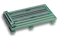
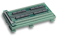
- DIN-100S:
100-pin SCSI-II termination board with DIN-rail mounting and 1 m ACL-102100 cable.
- DIN-96DI:
96-channel opto-isolated digital input board (0–24 VDC input range, 2.5 kV isolation).
- DIN-96DO:
96-channel opto-isolated digital output board with Darlington transistor drivers (up to 35 VDC, 350 mA/channel).
Cables:
- ACL-102100: 100-pin SCSI-II cable (1 m length, included with termination boards).
### 6. Installation & Setup
System Requirements:
- Available 32-bit PCI slot (5 V signaling)
- Compatible operating system (Windows or Linux)
- Administrative privileges for driver installation
Installation Steps:
1. Power off the host PC and disconnect peripherals.
2. Insert the PCI-7348 into an available PCI slot.
3. Secure the card and reconnect system power.
4. Upon boot, the PCI Plug-and-Play BIOS assigns I/O addresses and IRQ automatically.
5. Install ADLINK’s PCIS-DASK or other driver packages from the provided CD.
6. Connect external devices via the 100-pin SCSI-II connector or termination board.
Jumper Configuration:
- Jumpers JA1–JC2 control the power-on state (pull-high, pull-low, or floating) for each port.
- Default setting: all ports pulled low.
- EXTTRG (pin 99) and EVENT (pin 51) provide external trigger and event counter inputs.
Mounting Options:
- Standard PCI slot installation
- DIN-rail mounting via termination boards
### 7. Performance & Capabilities
Data Transfer:
- Programmed I/O mode
- Typical transfer rate: 1 MB/s
Timing & Counting:
- 32-bit cascaded timer for precise timing intervals
- 16-bit event counter for external pulse counting
- Adjustable edge detection (rising/falling)
Interrupt Handling:
- Dual interrupt system allows simultaneous handling of COS and timer events.
- COS detection latency depends on system interrupt response time.
Electrical Performance:
- High sink current (48 mA) enables direct driving of LEDs and relays.
- Output readback ensures accurate state verification.
Limitations:
- No optical isolation on the base card (use DIN-96DI/DO for isolation).
- Limited to 5 V TTL logic levels.
- External power outputs limited to 0.5 A per rail.
### 8. Standards & Compliance
- Bus Interface: PCI Local Bus Specification Rev. 2.1 compliant
- Logic Standard: 5 V TTL/CMOS compatible
- Safety & Environmental:
- Operating temperature: 0–60°C
- Storage temperature: –20–80°C
- Humidity: 5–95%, non-condensing
- EMC/EMI: Designed for industrial environments (meets CE and FCC Class A requirements when installed in compliant systems)
- Isolation: None on base card; available via optional DIN-96DI/DO boards (2.5 kV isolation)
### 9. Additional Information
Software Support:
- PCIS-DASK: Windows 98/NT/2000 device driver and DLL library for VB, VC++, Delphi, BC5.
- PCIS-DASK/X: Linux shared library for C/C++ development.
- PCIS-LVIEW: LabVIEW® driver with ready-to-use VIs.
- PCIS-VEE: HP VEE driver for graphical programming.
- DAQBench™: ActiveX control library for VB/VC++.
- PCIS-OPC: OPC server for SCADA integration.
- PCIS-ISG: ISaGRAF™ SoftPLC driver.
- PCIS-ICL: InControl™ driver for Windows NT.
Programming Interfaces:
- C/C++ libraries for DOS and Windows
- Visual Basic and Delphi DLL interfaces
- Example functions include:
- `_7348_Initial()`, `_7348_DI()`, `_7348_DO()`, `_7348_Config_Port()`
- `_7348_INT_Source_Control()`, `_7348_COSIRQ_Control()`
- `_7348_Timer_Start()`, `_7348_Cascaded_Timer()`, `_7348_CLR_IRQ()`
Maintenance & Support:
- Warranty: 2 years from shipment date (free repair for manufacturing defects)
- Exclusions: Damage from misuse, improper installation, or environmental factors
- Service Contact:
ADLINK Technology Inc.
9F, No. 166, Jian Yi Road, Chungho City, Taipei 235, Taiwan
Tel: +886-2-82265877 | Fax: +886-2-82265717
Email: service@adlinktech.com
Web: [www.adlinktech.com](http://www.adlinktech.com)
RMA Procedure:
- Obtain RMA form from ADLINK website.
- Return defective product with proof of purchase.
- Customer responsible for shipping to ADLINK; repaired items returned prepaid.
Maintenance Notes:
- Handle with ESD precautions.
- Avoid overloading power outputs.
- Use resettable fuses for protection.
- Periodically inspect connectors and cables for wear.
Product Lifecycle & Updates:
- Firmware and driver updates available via ADLINK’s support portal.
- Backward compatibility maintained across PCI-7348 and PCI-7396 series.
### Summary
The ADLINK PCI-7348 is a robust, high-current, 48-channel digital I/O card optimized for industrial automation and control. It combines flexible I/O configuration, high drive capability, and advanced interrupt features in a compact PCI form factor. With comprehensive software support across multiple platforms and optional isolated termination boards, the PCI-7348 provides a scalable and reliable solution for digital signal interfacing, event monitoring, and process control in industrial and laboratory environments.

### 1. Product Overview
Product Name: PCI-7348
Model: PCI-7348
Series: NuDAQ® PCI DIO Series
Article Number: PCI-7348
Manufacturer: ADLINK Technology Inc.
The ADLINK PCI-7348 is a high-current, 48-channel digital input/output (DIO) interface card designed for industrial automation, monitoring, and control applications. It belongs to ADLINK’s NuDAQ® family of PCI-based data acquisition and control products. The PCI-7348 provides robust TTL-compatible digital I/O capabilities with advanced interrupt handling, change-of-state (COS) detection, and output readback functionality. It is engineered for high reliability and performance in demanding industrial environments.
### 2. Key Features
- 48 TTL-Compatible Digital I/O Channels:
Provides 48 bidirectional digital lines configurable as input or output in 8-bit port groups.
- High Current Drive Capability:
Each output channel can source up to 15 mA and sink up to 48 mA, suitable for driving LEDs, relays, and other TTL/CMOS devices.
- Change-of-State (COS) Interrupt:
Generates an interrupt when any input bit changes state, enabling event-driven digital monitoring.
- Dual Interrupt System:
Two independent interrupt sources (INT1 and INT2) allow simultaneous handling of multiple event types such as COS, timer, or counter events.
- Output Status Readback:
Supports readback of output states for verification and closed-loop control.
- External Trigger Input:
Accepts an external trigger signal (EXTTRG, pin 99) to latch input data synchronously with external events.
- Programmable Timer/Counter:
Includes one 8254 programmable timer/counter chip providing a 32-bit timer and a 16-bit event counter for timing and counting applications.
- User-Configurable Power-On State:
Each port can be configured via jumpers to power up in a pulled-high, pulled-low, or floating state.
- Onboard Power Outputs:
Provides +5 V and +12 V outputs on the SCSI connector (protected by resettable fuses) for powering external circuits.
- Watchdog Timer:
32-bit watchdog timer ensures system reliability and can reset outputs or trigger interrupts on timeout.
- Compact PCI Form Factor:
Half-size PCI card (158 mm × 107 mm) compliant with PCI Bus Rev. 2.1.
### 3. Technical Specifications
Digital I/O:
- Number of Channels: 48 bidirectional (6 ports × 8 bits)
- Logic Standard: 5 V TTL compatible
- Power-On State: Input (default)
- Input Voltage Levels:
- Logic High: 2.0 V to 5.25 V
- Logic Low: 0.0 V to 0.8 V
- Input Current:
- High: 0.1 µA
- Low: –8 mA
- Output Voltage Levels:
- Logic High: ≥ 2.4 V (typical 3.3 V)
- Logic Low: ≤ 0.5 V
- Output Current:
- Source: 15 mA
- Sink: 48 mA
Interrupt System:
- Dual interrupt architecture (INT1 and INT2)
- COS detection on all input bits
- Programmable interrupt sources:
- INT1: COS P1&P2, P1C0, P1C3, or event counter
- INT2: COS P3&P4, P2C0, P2C3, or timer interrupt
- Programmable edge/level triggering
Timer/Counter:
- Device: 8254 programmable timer/counter
- Counters: 3 × 16-bit (Counter #0–#2)
- Cascaded 32-bit timer (Counters #1 and #2)
- Base Clock: 2 MHz internal oscillator
- Modes: 6 standard 8254 modes (rate generator, event counter, etc.)
- Event Counter Input: Pin 51 (EVENT)
- External Trigger Input: Pin 99 (EXTTRG)
Electrical & Mechanical:
- Bus Interface: 5 V PCI, Revision 2.1
- Connector: 100-pin SCSI-II female (AMP-787082-9)
- Dimensions: 158 mm (L) × 107 mm (H)
- Power Consumption: +5 V @ 350 mA (typical)
- Operating Temperature: 0°C to 60°C
- Storage Temperature: –20°C to 80°C
- Relative Humidity: 5% to 95%, non-condensing
Power Outputs (on connector):
- +5 V and +12 V outputs (0.5 A max each)
- Protected by resettable fuses
### 4. Functionality
Operation Principle:
The PCI-7348 emulates two Intel 8255 Programmable Peripheral Interface (PPI) chips, each providing three 8-bit ports (A, B, C). Each port can be independently configured as input or output. The card supports both polled and interrupt-driven I/O operations.
Use Cases & Applications:
- Industrial process monitoring and control
- Automated test systems
- LED and indicator driving
- Relay and solenoid control
- Parallel data transfer between systems
- TTL/DTL/CMOS logic signal interfacing
- Event counting and timing applications
Compatibility:
- Compatible with 5 V PCI slots
- Supported operating systems: DOS, Windows 95/98/NT/2000, Linux
- Software support via ADLINK PCIS-DASK, PCIS-LVIEW (LabVIEW®), PCIS-VEE (HP VEE), DAQBench™ ActiveX, and OPC/ISaGRAF/InControl drivers.
### 5. Components & Accessories
Included Items:
- PCI-7348 DIO card
- ADLINK software CD (drivers, libraries, manuals)
- Software Installation Guide
- User’s Manual
Optional Termination Boards:
- DIN-100S:
100-pin SCSI-II termination board with DIN-rail mounting and 1 m ACL-102100 cable.
- DIN-96DI:
96-channel opto-isolated digital input board (0–24 VDC input range, 2.5 kV isolation).
- DIN-96DO:
96-channel opto-isolated digital output board with Darlington transistor drivers (up to 35 VDC, 350 mA/channel).
Cables:
- ACL-102100: 100-pin SCSI-II cable (1 m length, included with termination boards).
### 6. Installation & Setup
System Requirements:
- Available 32-bit PCI slot (5 V signaling)
- Compatible operating system (Windows or Linux)
- Administrative privileges for driver installation
Installation Steps:
1. Power off the host PC and disconnect peripherals.
2. Insert the PCI-7348 into an available PCI slot.
3. Secure the card and reconnect system power.
4. Upon boot, the PCI Plug-and-Play BIOS assigns I/O addresses and IRQ automatically.
5. Install ADLINK’s PCIS-DASK or other driver packages from the provided CD.
6. Connect external devices via the 100-pin SCSI-II connector or termination board.
Jumper Configuration:
- Jumpers JA1–JC2 control the power-on state (pull-high, pull-low, or floating) for each port.
- Default setting: all ports pulled low.
- EXTTRG (pin 99) and EVENT (pin 51) provide external trigger and event counter inputs.
Mounting Options:
- Standard PCI slot installation
- DIN-rail mounting via termination boards
### 7. Performance & Capabilities
Data Transfer:
- Programmed I/O mode
- Typical transfer rate: 1 MB/s
Timing & Counting:
- 32-bit cascaded timer for precise timing intervals
- 16-bit event counter for external pulse counting
- Adjustable edge detection (rising/falling)
Interrupt Handling:
- Dual interrupt system allows simultaneous handling of COS and timer events.
- COS detection latency depends on system interrupt response time.
Electrical Performance:
- High sink current (48 mA) enables direct driving of LEDs and relays.
- Output readback ensures accurate state verification.
Limitations:
- No optical isolation on the base card (use DIN-96DI/DO for isolation).
- Limited to 5 V TTL logic levels.
- External power outputs limited to 0.5 A per rail.
### 8. Standards & Compliance
- Bus Interface: PCI Local Bus Specification Rev. 2.1 compliant
- Logic Standard: 5 V TTL/CMOS compatible
- Safety & Environmental:
- Operating temperature: 0–60°C
- Storage temperature: –20–80°C
- Humidity: 5–95%, non-condensing
- EMC/EMI: Designed for industrial environments (meets CE and FCC Class A requirements when installed in compliant systems)
- Isolation: None on base card; available via optional DIN-96DI/DO boards (2.5 kV isolation)
### 9. Additional Information
Software Support:
- PCIS-DASK: Windows 98/NT/2000 device driver and DLL library for VB, VC++, Delphi, BC5.
- PCIS-DASK/X: Linux shared library for C/C++ development.
- PCIS-LVIEW: LabVIEW® driver with ready-to-use VIs.
- PCIS-VEE: HP VEE driver for graphical programming.
- DAQBench™: ActiveX control library for VB/VC++.
- PCIS-OPC: OPC server for SCADA integration.
- PCIS-ISG: ISaGRAF™ SoftPLC driver.
- PCIS-ICL: InControl™ driver for Windows NT.
Programming Interfaces:
- C/C++ libraries for DOS and Windows
- Visual Basic and Delphi DLL interfaces
- Example functions include:
- `_7348_Initial()`, `_7348_DI()`, `_7348_DO()`, `_7348_Config_Port()`
- `_7348_INT_Source_Control()`, `_7348_COSIRQ_Control()`
- `_7348_Timer_Start()`, `_7348_Cascaded_Timer()`, `_7348_CLR_IRQ()`
Maintenance & Support:
- Warranty: 2 years from shipment date (free repair for manufacturing defects)
- Exclusions: Damage from misuse, improper installation, or environmental factors
- Service Contact:
ADLINK Technology Inc.
9F, No. 166, Jian Yi Road, Chungho City, Taipei 235, Taiwan
Tel: +886-2-82265877 | Fax: +886-2-82265717
Email: service@adlinktech.com
Web: [www.adlinktech.com](http://www.adlinktech.com)
RMA Procedure:
- Obtain RMA form from ADLINK website.
- Return defective product with proof of purchase.
- Customer responsible for shipping to ADLINK; repaired items returned prepaid.
Maintenance Notes:
- Handle with ESD precautions.
- Avoid overloading power outputs.
- Use resettable fuses for protection.
- Periodically inspect connectors and cables for wear.
Product Lifecycle & Updates:
- Firmware and driver updates available via ADLINK’s support portal.
- Backward compatibility maintained across PCI-7348 and PCI-7396 series.
### Summary
The ADLINK PCI-7348 is a robust, high-current, 48-channel digital I/O card optimized for industrial automation and control. It combines flexible I/O configuration, high drive capability, and advanced interrupt features in a compact PCI form factor. With comprehensive software support across multiple platforms and optional isolated termination boards, the PCI-7348 provides a scalable and reliable solution for digital signal interfacing, event monitoring, and process control in industrial and laboratory environments.
-
06-12.pdf
PDF Catalog
-
06-00.pdf
PDF Catalog
-
PCI-7348 7396_Manual_3.pdf
Manual
-
P7396 Manual.pdf
Manual
- DIN-100S-01 - 100pin SCSI-II termination board DIN rail w/o cable
- DIN-96DI-01 - 96 isolated DI DIN-rail board w/o cable
- DIN-96DO-01 - 96 isolated DO DIN-rail board w/o cable
- TB-96DI - 96 isolated DI termination board w/o cable
- TB-96DO - 96 isolated DO termination board w/o cable
- ACL-10253-1 - 2*50pin SCSI-II to 100pin SCSI-II cable 1m (PCI-7348/96)