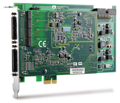
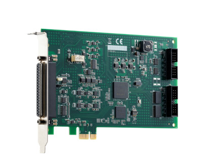
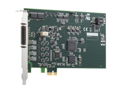
DIN-68S-01
SUCHEN SIE DIE PASSENDE
INDUSTRIELLE LÖSUNG?
Entdecken Sie Embedded-, Kommunikations- und Automatisierungslösungen für Ihre Anwendung.
- PCI Express x1 Interface: Fully compliant with PCIe x1 lane, supporting both 3.3 V and 5 V signaling environments.
- High‑Resolution Analog Input: 16‑bit A/D converter with no missing codes, supporting 16 single‑ended or 8 differential channels.
- Sampling Rate: Up to 250 kS/s aggregate throughput.
- Programmable Input Ranges: Bipolar ±10 V, ±5 V, ±2.5 V, ±1.25 V and unipolar 0–10 V, 0–5 V, 0–2.5 V, 0–1.25 V.
- Programmable Gain: x1, x2, x4, x8 with per‑channel configuration via a 512‑entry channel gain queue.
- Auto‑Calibration: Fully automatic calibration with onboard 5 V reference (±2 ppm/°C).
- Triggering: Supports software, external analog, external digital, and SSI triggers with multiple trigger modes (pre‑, post‑, middle‑, delay‑trigger).
- FIFO Buffers: 1 k‑sample A/D FIFO for efficient data buffering.
- Digital I/O: 24‑channel TTL‑compatible programmable I/O (8255 PIO).
- Timers/Counters: Two 16‑bit general‑purpose up/down counters with 40 MHz base clock and external clock up to 10 MHz.
- Scatter‑Gather DMA: High‑speed bus‑mastering DMA with scatter/gather capability for efficient data transfer.
- System Synchronization Interface (SSI): Enables multi‑card synchronization for simultaneous sampling.
- Software Support: Drivers and SDKs for Windows 7/8 x86/x64 and Linux; compatible with LabVIEW®, MATLAB®, C/C++, Visual Basic, and Visual Studio .NET.
- Utility Software: AD‑Logger for data logging and configuration.
- Plug‑and‑Play Configuration: No jumpers required; automatic resource allocation.
- High‑Resolution Analog Input: 16‑bit A/D converter with no missing codes, supporting 16 single‑ended or 8 differential channels.
- Sampling Rate: Up to 250 kS/s aggregate throughput.
- Programmable Input Ranges: Bipolar ±10 V, ±5 V, ±2.5 V, ±1.25 V and unipolar 0–10 V, 0–5 V, 0–2.5 V, 0–1.25 V.
- Programmable Gain: x1, x2, x4, x8 with per‑channel configuration via a 512‑entry channel gain queue.
- Auto‑Calibration: Fully automatic calibration with onboard 5 V reference (±2 ppm/°C).
- Triggering: Supports software, external analog, external digital, and SSI triggers with multiple trigger modes (pre‑, post‑, middle‑, delay‑trigger).
- FIFO Buffers: 1 k‑sample A/D FIFO for efficient data buffering.
- Digital I/O: 24‑channel TTL‑compatible programmable I/O (8255 PIO).
- Timers/Counters: Two 16‑bit general‑purpose up/down counters with 40 MHz base clock and external clock up to 10 MHz.
- Scatter‑Gather DMA: High‑speed bus‑mastering DMA with scatter/gather capability for efficient data transfer.
- System Synchronization Interface (SSI): Enables multi‑card synchronization for simultaneous sampling.
- Software Support: Drivers and SDKs for Windows 7/8 x86/x64 and Linux; compatible with LabVIEW®, MATLAB®, C/C++, Visual Basic, and Visual Studio .NET.
- Utility Software: AD‑Logger for data logging and configuration.
- Plug‑and‑Play Configuration: No jumpers required; automatic resource allocation.
Comprehensive Product Summary: ADLINK DAQe‑2213 PCI Express Data Acquisition Card
*(Approx. 3000 tokens / ~12,000 characters)*
### 1. Product Overview
Product Name: DAQe‑2213
Model: DAQe‑2213
Series: DAQ‑/DAQe‑2213/2214 Multi‑Function Data Acquisition Series
Article Number: DAQe‑2213
Manufacturer: ADLINK Technology Inc.
The ADLINK DAQe‑2213 is a high‑performance, low‑cost, multifunction PCI Express (PCIe) data acquisition (DAQ) card designed for precision analog and digital signal measurement and control. It belongs to ADLINK’s DAQ‑2000 family and provides up to 16 single‑ended or 8 differential analog input channels with 16‑bit resolution and a maximum sampling rate of 250 kS/s. The card integrates 24 channels of TTL digital I/O, two 16‑bit general‑purpose timers/counters, and supports advanced triggering, auto‑calibration, and synchronization through ADLINK’s System Synchronization Interface (SSI).
### 2. Key Features
- PCI Express x1 Interface: Fully compliant with PCIe x1 lane, supporting both 3.3 V and 5 V signaling environments.
- High‑Resolution Analog Input: 16‑bit A/D converter with no missing codes, supporting 16 single‑ended or 8 differential channels.
- Sampling Rate: Up to 250 kS/s aggregate throughput.
- Programmable Input Ranges: Bipolar ±10 V, ±5 V, ±2.5 V, ±1.25 V and unipolar 0–10 V, 0–5 V, 0–2.5 V, 0–1.25 V.
- Programmable Gain: x1, x2, x4, x8 with per‑channel configuration via a 512‑entry channel gain queue.
- Auto‑Calibration: Fully automatic calibration with onboard 5 V reference (±2 ppm/°C).
- Triggering: Supports software, external analog, external digital, and SSI triggers with multiple trigger modes (pre‑, post‑, middle‑, delay‑trigger).
- FIFO Buffers: 1 k‑sample A/D FIFO for efficient data buffering.
- Digital I/O: 24‑channel TTL‑compatible programmable I/O (8255 PIO).
- Timers/Counters: Two 16‑bit general‑purpose up/down counters with 40 MHz base clock and external clock up to 10 MHz.
- Scatter‑Gather DMA: High‑speed bus‑mastering DMA with scatter/gather capability for efficient data transfer.
- System Synchronization Interface (SSI): Enables multi‑card synchronization for simultaneous sampling.
- Software Support: Drivers and SDKs for Windows 7/8 x86/x64 and Linux; compatible with LabVIEW®, MATLAB®, C/C++, Visual Basic, and Visual Studio .NET.
- Utility Software: AD‑Logger for data logging and configuration.
- Plug‑and‑Play Configuration: No jumpers required; automatic resource allocation.
### 3. Technical Specifications
Analog Input (AI):
- Channels: 16 SE or 8 DI (software‑selectable per channel)
- Resolution: 16 bits, no missing codes
- Max Sampling Rate: 250 kS/s
- Input Coupling: DC
- Input Ranges:
- Bipolar: ±10 V, ±5 V, ±2.5 V, ±1.25 V
- Unipolar: 0–10 V, 0–5 V, 0–2.5 V, 0–1.25 V
- Programmable Gain: 1, 2, 4, 8
- Channel Gain Queue: 512 entries
- Offset Error: ±1 mV after calibration
- Gain Error: ±0.06 % FSR (typical)
- Input Impedance: 1 GΩ / 100 pF
- Overvoltage Protection: ±30 V (power on), ±15 V (power off)
- Input Bandwidth: up to 760 kHz (small‑signal, ±10 V range)
- Common‑Mode Rejection Ratio (DC–60 Hz): up to 93 dB
- Settling Time: 4 µs to 0.01 % error
- FIFO Buffer: 1 k samples
- Data Transfer: Polling or scatter‑gather DMA
Digital I/O:
- 24 channels, TTL‑compatible (8255 PIO)
- Programmable direction per port (A, B, C)
- Logic Levels:
- Input Low ≤ 0.8 V, High ≥ 2.0 V
- Output Low ≤ 0.5 V @ 8 mA, High ≥ 2.7 V @ 400 µA
Timer/Counter:
- Channels: 2 independent 16‑bit up/down counters
- Base Clock: 40 MHz internal, 10 MHz external max
- Compatibility: TTL
- Modes: 8 programmable modes (event counting, pulse generation, period/pulse‑width measurement, etc.)
General Specifications:
- Auto‑Calibration: Yes (+5 V reference, ±2 ppm/°C)
- Dimensions: 168 mm × 107 mm (6.55 " × 4.17 ") excluding connectors
- Connectors: Two 68‑pin VHDCI female connectors
- Operating Temperature: 0 °C to 55 °C (32 °F to 131 °F)
- Storage Temperature: –20 °C to 70 °C (–4 °F to 158 °F)
- Humidity: 5 % to 95 %, non‑condensing
- Power Requirements (typical): +3.3 V @ 0.84 A, +12 V @ 0.604 A
### 4. Functionality
The DAQe‑2213 performs high‑precision analog‑to‑digital conversion for measurement and monitoring applications. Each channel can be configured independently for single‑ended or differential input, with programmable gain and range. The onboard A/D converter digitizes analog signals into 16‑bit data, buffered in a 1 k‑sample FIFO, and transferred to host memory via DMA or polling.
Use Cases and Applications:
- Automotive and cable testing
- Transient signal capture and analysis
- Automated Test Equipment (ATE)
- Laboratory and industrial automation
- Biotech and biomedical instrumentation
Compatibility:
- Operating Systems: Windows 7/8 (32/64‑bit), Linux
- Development Environments: LabVIEW®, MATLAB®, C/C++, Visual Basic, Visual Studio .NET
- Synchronization: Multiple DAQe‑2213/2214 cards can be linked via SSI bus for simultaneous sampling.
### 5. Components & Accessories
Included Items:
- DAQe‑2213 PCIe data acquisition card
- ADLINK All‑in‑One software CD (includes drivers and utilities)
- Software Installation Guide
- User’s Manual
Optional Accessories:
- Terminal Boards: DIN‑68S‑01, ACL‑10568‑1
- Cables: ACL‑SSI‑2/3/4 (for multi‑card synchronization)
- Connectors: Two 68‑pin VHDCI female connectors (AMP 787254‑1 compatible)
### 6. Installation & Setup
Requirements:
- Available PCI Express x1 slot (3.3 V or 5 V compatible)
- Supported OS and driver installation from ADLINK CD
Mounting & Configuration:
- Plug‑and‑Play PCIe installation; no jumpers required.
- Automatic IRQ and I/O address assignment by system BIOS.
- Use ADLINK PCI_SCAN utility to verify system configuration.
Signal Connections:
- Two 68‑pin VHDCI connectors (CN1 and CN2) for AI, DIO, and timing signals.
- CN1 provides analog inputs and trigger lines; CN2 provides digital I/O, timers, and SSI signals.
- Supports single‑ended (RSE/NRSE) and differential input configurations.
Setup Procedure:
1. Power off the PC and insert the DAQe‑2213 into an available PCIe slot.
2. Secure the card and reconnect power.
3. Install drivers and software from the ADLINK CD.
4. Use AD‑Logger or SDK tools to configure channels, ranges, and trigger modes.
### 7. Performance & Capabilities
Analog Input Performance:
- Sampling Rate: 250 kS/s aggregate
- Resolution: 16 bits (1 LSB ≈ 305 µV at ±10 V range)
- Noise: 0.8–1.2 LSBrms (typical)
- CMRR: 83–93 dB depending on range
- Bandwidth: up to 760 kHz (small signal)
- Settling Time: 4 µs to 0.01 % error
Digital I/O Performance:
- 24 TTL channels with programmable direction
- Supports synchronous digital inputs sampled with analog signals
Timer/Counter Performance:
- 16‑bit resolution, 40 MHz base clock
- External clock up to 10 MHz
- Supports event counting, pulse generation, period and pulse‑width measurement
Efficiency & Limitations:
- High‑speed DMA reduces CPU load and maximizes PCIe bandwidth.
- FIFO buffer prevents data loss at high sampling rates.
- Maximum analog input rate limited to 250 kS/s aggregate across channels.
### 8. Standards & Compliance
- Bus Interface: PCI Express x1 compliant
- Voltage Compatibility: 3.3 V and 5 V PCI bus operation
- Environmental Compliance: Operating 0–55 °C, Storage –20–70 °C, 5–95 % RH non‑condensing
- Safety & Reliability: Overvoltage protection ±30 V (on), ±15 V (off)
- Calibration Reference: 5.000 V ± 2 ppm/°C, 6 ppm/1000 h stability
- Regulatory: Designed to meet industrial EMC and safety standards for data acquisition equipment.
### 9. Additional Information
Warranty:
- Standard two‑year limited warranty (one year in China).
- Covers manufacturing defects and hardware failures under normal use.
- Excludes damage from misuse, improper installation, or environmental factors.
Support & Service:
- Global technical support offices in Taiwan, USA, Europe, Singapore, India, and China.
- Email: service@adlinktech.com

*(Approx. 3000 tokens / ~12,000 characters)*
### 1. Product Overview
Product Name: DAQe‑2213
Model: DAQe‑2213
Series: DAQ‑/DAQe‑2213/2214 Multi‑Function Data Acquisition Series
Article Number: DAQe‑2213
Manufacturer: ADLINK Technology Inc.
The ADLINK DAQe‑2213 is a high‑performance, low‑cost, multifunction PCI Express (PCIe) data acquisition (DAQ) card designed for precision analog and digital signal measurement and control. It belongs to ADLINK’s DAQ‑2000 family and provides up to 16 single‑ended or 8 differential analog input channels with 16‑bit resolution and a maximum sampling rate of 250 kS/s. The card integrates 24 channels of TTL digital I/O, two 16‑bit general‑purpose timers/counters, and supports advanced triggering, auto‑calibration, and synchronization through ADLINK’s System Synchronization Interface (SSI).
### 2. Key Features
- PCI Express x1 Interface: Fully compliant with PCIe x1 lane, supporting both 3.3 V and 5 V signaling environments.
- High‑Resolution Analog Input: 16‑bit A/D converter with no missing codes, supporting 16 single‑ended or 8 differential channels.
- Sampling Rate: Up to 250 kS/s aggregate throughput.
- Programmable Input Ranges: Bipolar ±10 V, ±5 V, ±2.5 V, ±1.25 V and unipolar 0–10 V, 0–5 V, 0–2.5 V, 0–1.25 V.
- Programmable Gain: x1, x2, x4, x8 with per‑channel configuration via a 512‑entry channel gain queue.
- Auto‑Calibration: Fully automatic calibration with onboard 5 V reference (±2 ppm/°C).
- Triggering: Supports software, external analog, external digital, and SSI triggers with multiple trigger modes (pre‑, post‑, middle‑, delay‑trigger).
- FIFO Buffers: 1 k‑sample A/D FIFO for efficient data buffering.
- Digital I/O: 24‑channel TTL‑compatible programmable I/O (8255 PIO).
- Timers/Counters: Two 16‑bit general‑purpose up/down counters with 40 MHz base clock and external clock up to 10 MHz.
- Scatter‑Gather DMA: High‑speed bus‑mastering DMA with scatter/gather capability for efficient data transfer.
- System Synchronization Interface (SSI): Enables multi‑card synchronization for simultaneous sampling.
- Software Support: Drivers and SDKs for Windows 7/8 x86/x64 and Linux; compatible with LabVIEW®, MATLAB®, C/C++, Visual Basic, and Visual Studio .NET.
- Utility Software: AD‑Logger for data logging and configuration.
- Plug‑and‑Play Configuration: No jumpers required; automatic resource allocation.
### 3. Technical Specifications
Analog Input (AI):
- Channels: 16 SE or 8 DI (software‑selectable per channel)
- Resolution: 16 bits, no missing codes
- Max Sampling Rate: 250 kS/s
- Input Coupling: DC
- Input Ranges:
- Bipolar: ±10 V, ±5 V, ±2.5 V, ±1.25 V
- Unipolar: 0–10 V, 0–5 V, 0–2.5 V, 0–1.25 V
- Programmable Gain: 1, 2, 4, 8
- Channel Gain Queue: 512 entries
- Offset Error: ±1 mV after calibration
- Gain Error: ±0.06 % FSR (typical)
- Input Impedance: 1 GΩ / 100 pF
- Overvoltage Protection: ±30 V (power on), ±15 V (power off)
- Input Bandwidth: up to 760 kHz (small‑signal, ±10 V range)
- Common‑Mode Rejection Ratio (DC–60 Hz): up to 93 dB
- Settling Time: 4 µs to 0.01 % error
- FIFO Buffer: 1 k samples
- Data Transfer: Polling or scatter‑gather DMA
Digital I/O:
- 24 channels, TTL‑compatible (8255 PIO)
- Programmable direction per port (A, B, C)
- Logic Levels:
- Input Low ≤ 0.8 V, High ≥ 2.0 V
- Output Low ≤ 0.5 V @ 8 mA, High ≥ 2.7 V @ 400 µA
Timer/Counter:
- Channels: 2 independent 16‑bit up/down counters
- Base Clock: 40 MHz internal, 10 MHz external max
- Compatibility: TTL
- Modes: 8 programmable modes (event counting, pulse generation, period/pulse‑width measurement, etc.)
General Specifications:
- Auto‑Calibration: Yes (+5 V reference, ±2 ppm/°C)
- Dimensions: 168 mm × 107 mm (6.55 " × 4.17 ") excluding connectors
- Connectors: Two 68‑pin VHDCI female connectors
- Operating Temperature: 0 °C to 55 °C (32 °F to 131 °F)
- Storage Temperature: –20 °C to 70 °C (–4 °F to 158 °F)
- Humidity: 5 % to 95 %, non‑condensing
- Power Requirements (typical): +3.3 V @ 0.84 A, +12 V @ 0.604 A
### 4. Functionality
The DAQe‑2213 performs high‑precision analog‑to‑digital conversion for measurement and monitoring applications. Each channel can be configured independently for single‑ended or differential input, with programmable gain and range. The onboard A/D converter digitizes analog signals into 16‑bit data, buffered in a 1 k‑sample FIFO, and transferred to host memory via DMA or polling.
Use Cases and Applications:
- Automotive and cable testing
- Transient signal capture and analysis
- Automated Test Equipment (ATE)
- Laboratory and industrial automation
- Biotech and biomedical instrumentation
Compatibility:
- Operating Systems: Windows 7/8 (32/64‑bit), Linux
- Development Environments: LabVIEW®, MATLAB®, C/C++, Visual Basic, Visual Studio .NET
- Synchronization: Multiple DAQe‑2213/2214 cards can be linked via SSI bus for simultaneous sampling.
### 5. Components & Accessories
Included Items:
- DAQe‑2213 PCIe data acquisition card
- ADLINK All‑in‑One software CD (includes drivers and utilities)
- Software Installation Guide
- User’s Manual
Optional Accessories:
- Terminal Boards: DIN‑68S‑01, ACL‑10568‑1
- Cables: ACL‑SSI‑2/3/4 (for multi‑card synchronization)
- Connectors: Two 68‑pin VHDCI female connectors (AMP 787254‑1 compatible)
### 6. Installation & Setup
Requirements:
- Available PCI Express x1 slot (3.3 V or 5 V compatible)
- Supported OS and driver installation from ADLINK CD
Mounting & Configuration:
- Plug‑and‑Play PCIe installation; no jumpers required.
- Automatic IRQ and I/O address assignment by system BIOS.
- Use ADLINK PCI_SCAN utility to verify system configuration.
Signal Connections:
- Two 68‑pin VHDCI connectors (CN1 and CN2) for AI, DIO, and timing signals.
- CN1 provides analog inputs and trigger lines; CN2 provides digital I/O, timers, and SSI signals.
- Supports single‑ended (RSE/NRSE) and differential input configurations.
Setup Procedure:
1. Power off the PC and insert the DAQe‑2213 into an available PCIe slot.
2. Secure the card and reconnect power.
3. Install drivers and software from the ADLINK CD.
4. Use AD‑Logger or SDK tools to configure channels, ranges, and trigger modes.
### 7. Performance & Capabilities
Analog Input Performance:
- Sampling Rate: 250 kS/s aggregate
- Resolution: 16 bits (1 LSB ≈ 305 µV at ±10 V range)
- Noise: 0.8–1.2 LSBrms (typical)
- CMRR: 83–93 dB depending on range
- Bandwidth: up to 760 kHz (small signal)
- Settling Time: 4 µs to 0.01 % error
Digital I/O Performance:
- 24 TTL channels with programmable direction
- Supports synchronous digital inputs sampled with analog signals
Timer/Counter Performance:
- 16‑bit resolution, 40 MHz base clock
- External clock up to 10 MHz
- Supports event counting, pulse generation, period and pulse‑width measurement
Efficiency & Limitations:
- High‑speed DMA reduces CPU load and maximizes PCIe bandwidth.
- FIFO buffer prevents data loss at high sampling rates.
- Maximum analog input rate limited to 250 kS/s aggregate across channels.
### 8. Standards & Compliance
- Bus Interface: PCI Express x1 compliant
- Voltage Compatibility: 3.3 V and 5 V PCI bus operation
- Environmental Compliance: Operating 0–55 °C, Storage –20–70 °C, 5–95 % RH non‑condensing
- Safety & Reliability: Overvoltage protection ±30 V (on), ±15 V (off)
- Calibration Reference: 5.000 V ± 2 ppm/°C, 6 ppm/1000 h stability
- Regulatory: Designed to meet industrial EMC and safety standards for data acquisition equipment.
### 9. Additional Information
Warranty:
- Standard two‑year limited warranty (one year in China).
- Covers manufacturing defects and hardware failures under normal use.
- Excludes damage from misuse, improper installation, or environmental factors.
Support & Service:
- Global technical support offices in Taiwan, USA, Europe, Singapore, India, and China.
- Email: service@adlinktech.com
-
DAQ_DAQe_2213_2214_Datasheet.pdf
PDF Catalog

- DIN-68S-01 - 68pin SCSI-II termination board DIN rail w/o cable
- ACL-10568-1 - SCSI-VHDCI cable 1m for DAQ series
- ACL-10568-2 - SCSI-VHDCI cable 2m for DAQ series
- ACL-10568-3 - SCSI-VHDCI cable 3m for DAQ series