ACL-10120-1
LOOKING FOR THE RIGHT
INDUSTRIAL SOLUTION?
Discover embedded, communication and automation solutions tailored to your application.
- Universal Screw Terminal Interface:
Provides 40 screw terminal points arranged as two 20-pin connectors (CNA and CNB), allowing direct connection to 20-pin flat ribbon cables.
- Signal Conditioning Capability:
Designed with reserved circuit pads for passive components (resistors and capacitors), enabling users to implement custom signal conditioning circuits such as:
- Low-pass filters
- Voltage attenuators
- Current-to-voltage converters (e.g., 0–20 mA to 0–5 VDC)
- Flexible Configuration:
Each channel pair (A1–A2, B1–B2, etc.) can be configured for straight-through connection, attenuation, or filtering by populating or shorting specific resistor and capacitor positions.
- Compatibility:
Fully compatible with ADLINK’s ACL and PCI series DAQ cards, including ACL-8312/8316, ACL-8216, ACL-6126, and ACL-7120.
- Ease of Installation:
Equipped with nylon standoffs for secure table-top or panel mounting.
Includes two 20-pin flat cables (ACL-10120-1) for direct connection to DAQ cards.
- Low-Cost, High-Reliability Design:
Provides a cost-effective and durable solution for laboratory, industrial, and educational signal interfacing applications.
- TTL/CMOS Signal Compatibility:
Supports TTL/CMOS-level signals for direct interfacing with digital I/O ports of ADLINK DAQ cards.
Provides 40 screw terminal points arranged as two 20-pin connectors (CNA and CNB), allowing direct connection to 20-pin flat ribbon cables.
- Signal Conditioning Capability:
Designed with reserved circuit pads for passive components (resistors and capacitors), enabling users to implement custom signal conditioning circuits such as:
- Low-pass filters
- Voltage attenuators
- Current-to-voltage converters (e.g., 0–20 mA to 0–5 VDC)
- Flexible Configuration:
Each channel pair (A1–A2, B1–B2, etc.) can be configured for straight-through connection, attenuation, or filtering by populating or shorting specific resistor and capacitor positions.
- Compatibility:
Fully compatible with ADLINK’s ACL and PCI series DAQ cards, including ACL-8312/8316, ACL-8216, ACL-6126, and ACL-7120.
- Ease of Installation:
Equipped with nylon standoffs for secure table-top or panel mounting.
Includes two 20-pin flat cables (ACL-10120-1) for direct connection to DAQ cards.
- Low-Cost, High-Reliability Design:
Provides a cost-effective and durable solution for laboratory, industrial, and educational signal interfacing applications.
- TTL/CMOS Signal Compatibility:
Supports TTL/CMOS-level signals for direct interfacing with digital I/O ports of ADLINK DAQ cards.
Comprehensive Product Summary – ADLINK NuDAQ® ACLD-9178 Termination Board
### 1. Product Overview
Product Name: ACLD-9178
Model Number: ACLD-9178
Series: NuDAQ® ACLD Series Termination Boards
Article Number: ACLD-9178
Manufacturer: ADLINK Technology Inc.
Country of Origin: Taiwan, R.O.C.
Manufacturer Address: 9F, No. 166, Jian Yi Road, Chungho City, Taipei 235, Taiwan
Website: [www.adlinktech.com](http://www.adlinktech.com)
Support Contact: service@adlinktech.com
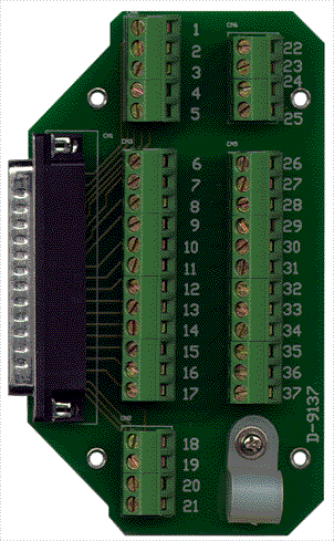
The ADLINK NuDAQ® ACLD-9178 is a universal screw terminal panel designed for convenient signal interfacing and conditioning in data acquisition and control systems. It serves as a termination and signal conditioning interface for ADLINK’s ACL and PCI series data acquisition cards, providing a flexible platform for constructing low-pass filters, voltage attenuators, and current-to-voltage converters. The ACLD-9178 is part of ADLINK’s ACLD family of termination boards, which includes models such as ACLD-9185, ACLD-9182A, ACLD-8125, ACLD-9188, and ACLD-9138.
### 2. Key Features
- Universal Screw Terminal Interface:
Provides 40 screw terminal points arranged as two 20-pin connectors (CNA and CNB), allowing direct connection to 20-pin flat ribbon cables.
- Signal Conditioning Capability:
Designed with reserved circuit pads for passive components (resistors and capacitors), enabling users to implement custom signal conditioning circuits such as:
- Low-pass filters
- Voltage attenuators
- Current-to-voltage converters (e.g., 0–20 mA to 0–5 VDC)
- Flexible Configuration:
Each channel pair (A1–A2, B1–B2, etc.) can be configured for straight-through connection, attenuation, or filtering by populating or shorting specific resistor and capacitor positions.
- Compatibility:
Fully compatible with ADLINK’s ACL and PCI series DAQ cards, including ACL-8312/8316, ACL-8216, ACL-6126, and ACL-7120.
- Ease of Installation:
Equipped with nylon standoffs for secure table-top or panel mounting.
Includes two 20-pin flat cables (ACL-10120-1) for direct connection to DAQ cards.
- Low-Cost, High-Reliability Design:
Provides a cost-effective and durable solution for laboratory, industrial, and educational signal interfacing applications.
- TTL/CMOS Signal Compatibility:
Supports TTL/CMOS-level signals for direct interfacing with digital I/O ports of ADLINK DAQ cards.
### 3. Technical Specifications
| Parameter | Specification |
|----------------|-------------------|
| Board Type | Universal screw terminal panel for signal conditioning |
| Connectors | Two 20-pin flat cable connectors (CNA, CNB) |
| Terminal Points | 40 screw terminals (A1–A20, B1–B20) |
| Included Cable | Two 20-pin flat cables (ACL-10120-1) |
| Dimensions | 102 mm × 114 mm |
| Mounting | Table-top or panel mounting with nylon standoffs |
| Material | FR-4 PCB with plated through-holes and screw terminal blocks |
| Signal Compatibility | TTL/CMOS digital signals, analog voltage/current signals |
| Supported Circuits | Passive RC filters, voltage dividers, current shunts |
| Operating Environment | Standard laboratory or industrial environment |
| Manufacturer | ADLINK Technology Inc. |
### 4. Functionality
The ACLD-9178 functions as a termination and signal conditioning interface between ADLINK data acquisition cards and external field signals. It provides screw terminals for easy wiring and allows users to implement custom passive circuits directly on the board.
Typical Functional Configurations:
1. Straight-Through Connection (Default):
- R1A = 0 Ω (short)
- R1B and C1 = open
- Provides direct signal pass-through from input to output.
2. Single-Ended Voltage Attenuator:
- R1A and R1B form a voltage divider.
- Attenuation ratio = R1B / (R1A + R1B).
- Example: For 10:1 attenuation, R1A = 9 kΩ, R1B = 1 kΩ.
3. Low-Pass Filter (Single-Ended Input):
- R1A and C1 form an RC filter.
- Cutoff frequency (f₃dB) = 1 / (2πR1A·C1).
- Example: For 1.6 kHz cutoff, R1A = 10 kΩ, C1 = 0.01 µF.
4. 0–20 mA Current Loop Input:
- R1A = 0 Ω (short), C1 = open, R1B = 250 Ω (0.05% tolerance).
- Converts 0–20 mA current signal to 0–5 VDC voltage signal.
Applications:
- Analog signal conditioning for DAQ systems
- Sensor signal interfacing (voltage, current, or filtered signals)
- Laboratory instrumentation and testing setups
- Industrial process monitoring and control
- Educational and research environments for circuit prototyping
### 5. Components & Accessories
Included Items:
- ACLD-9178 screw terminal board
- Two 20-pin flat ribbon cables (ACL-10120-1)
- Nylon standoffs for mounting
- User’s manual and documentation
Connectors:
- CNA (20-pin): Channels A1–A20
- CNB (20-pin): Channels B1–B20
- Each connector corresponds to a 20-pin flat cable header for connection to DAQ cards.
Optional Accessories:
- Additional flat ribbon cables (ACL-10120-1 or ACL-10120-2)
- External enclosures or DIN-rail mounting kits
- Replacement screw terminal blocks
### 6. Installation & Setup
Installation Steps:
1. Unpack and Inspect:
Verify that the ACLD-9178 board, cables, and standoffs are included and undamaged.
2. Mounting:
Use the provided nylon standoffs to secure the board on a flat surface or panel.
3. Connection to DAQ Card:
- Connect the 20-pin flat cable from the DAQ card’s I/O port to the ACLD-9178’s CNA or CNB connector.
- Ensure correct pin alignment to prevent signal inversion.
4. Signal Wiring:
- Connect external signals to the corresponding screw terminals (A1–A20, B1–B20).
- Observe proper grounding and shielding practices for analog signals.
5. Circuit Configuration:
- Populate resistor and capacitor pads as required for desired signal conditioning (attenuation, filtering, etc.).
- Default configuration is straight-through (no components installed).
6. Verification:
- Check continuity and signal integrity before applying power.
- Confirm correct operation using the DAQ software or test signals.
Configuration Notes:
- The board supports both single-ended and differential signal wiring depending on the DAQ card used.
- Ensure that the DAQ card’s input range and impedance match the conditioning circuit design.
### 7. Performance & Capabilities
Electrical Performance:
- Signal Path: Passive, low-noise, and low-distortion path suitable for analog and digital signals.
- Frequency Response: Determined by user-installed RC components; can be configured for low-pass filtering up to several kHz.
- Voltage Handling: Compatible with standard DAQ input ranges (±5 V, ±10 V).
- Current Handling: Supports current loop conversion (0–20 mA to 0–5 VDC).
- Impedance: Defined by user-selected resistors; typically high input impedance for voltage signals.
Mechanical Performance:
- Durability: Industrial-grade screw terminals rated for repeated connections.
- Mounting Stability: Nylon standoffs provide electrical isolation and mechanical support.
- Compact Size: 102 × 114 mm footprint allows integration into control panels or test benches.
Limitations:
- Passive-only design (no active amplification or isolation).
- Not intended for high-frequency (>100 kHz) signal conditioning.
- Requires user-supplied resistors and capacitors for custom circuits.
### 8. Standards & Compliance
Certifications and Compliance:
- Designed and manufactured by ADLINK Technology Inc. under ISO-certified quality systems.
- Complies with CE and FCC standards for electromagnetic compatibility (EMC).
- RoHS-compliant materials and lead-free soldering processes.
- Meets industrial-grade PCB manufacturing standards (FR-4 substrate, plated through-holes).
Industry Compatibility:
- Fully compatible with ADLINK’s NuDAQ® and ACL series data acquisition systems.
- Supports standard 20-pin flat cable pinouts used across ADLINK’s analog and digital I/O modules.
### 9. Additional Information
Warranty:
- Standard ADLINK limited warranty of two years from the date of shipment (one year for products purchased in China).
- Covers defects in materials and workmanship under normal use.
- Excludes damage due to misuse, unauthorized repair, or environmental factors.
Support & Service:
- Technical Support: nudaq@adlink.com.tw
- Sales & Service: service@adlink.com.tw
- Telephone: +886-2-82265877
- Fax: +886-2-82265717
- RMA Service: [http://rma.adlinktech.com/policy](http://rma.adlinktech.com/policy)
Maintenance:
- Periodically inspect screw terminals for oxidation or loose connections.
- Clean PCB surface with antistatic brush if dust accumulates.
- Verify integrity of flat cable connections during routine system maintenance.
Software & Updates:
- The ACLD-9178 itself requires no firmware or software.
- Compatible DAQ cards can be configured using ADLINK’s NuDAQ driver suite and application software.
Environmental Considerations:
- Store in a dry, dust-free environment.
- Avoid exposure to high humidity, corrosive chemicals, or extreme temperatures.
- Recommended operating temperature: 0°C to 50°C.
### Summary
The ADLINK NuDAQ® ACLD-9178 is a versatile, low-cost termination and signal conditioning board designed for use with ADLINK’s ACL and PCI series data acquisition cards. It provides a convenient interface between field wiring and DAQ hardware, allowing users to implement custom passive circuits for signal filtering, attenuation, or current conversion. With its dual 20-pin connectors, 40 screw terminals, and flexible configuration options, the ACLD-9178 is ideal for laboratory, industrial, and educational applications requiring reliable and customizable signal interfacing.
Its robust construction, ease of installation, and compatibility with a wide range of ADLINK DAQ products make it a dependable component in any data acquisition or control system. The inclusion of flat cables and mounting accessories ensures quick setup, while the open design allows engineers to tailor signal conditioning to specific measurement requirements.
Keywords for Technical Search Optimization:
ADLINK ACLD-9178, NuDAQ termination board, signal conditioning panel, low-pass filter board, voltage attenuator, current-to-voltage converter, 20-pin screw terminal, DAQ interface board, ACL-8312 compatible, ACL-8216 interface, ACL-6126 termination, ACL-7120 accessory, ADLINK termination panel, passive signal conditioning, industrial DAQ wiring board.

### 1. Product Overview
Product Name: ACLD-9178
Model Number: ACLD-9178
Series: NuDAQ® ACLD Series Termination Boards
Article Number: ACLD-9178
Manufacturer: ADLINK Technology Inc.
Country of Origin: Taiwan, R.O.C.
Manufacturer Address: 9F, No. 166, Jian Yi Road, Chungho City, Taipei 235, Taiwan
Website: [www.adlinktech.com](http://www.adlinktech.com)
Support Contact: service@adlinktech.com
The ADLINK NuDAQ® ACLD-9178 is a universal screw terminal panel designed for convenient signal interfacing and conditioning in data acquisition and control systems. It serves as a termination and signal conditioning interface for ADLINK’s ACL and PCI series data acquisition cards, providing a flexible platform for constructing low-pass filters, voltage attenuators, and current-to-voltage converters. The ACLD-9178 is part of ADLINK’s ACLD family of termination boards, which includes models such as ACLD-9185, ACLD-9182A, ACLD-8125, ACLD-9188, and ACLD-9138.
### 2. Key Features
- Universal Screw Terminal Interface:
Provides 40 screw terminal points arranged as two 20-pin connectors (CNA and CNB), allowing direct connection to 20-pin flat ribbon cables.
- Signal Conditioning Capability:
Designed with reserved circuit pads for passive components (resistors and capacitors), enabling users to implement custom signal conditioning circuits such as:
- Low-pass filters
- Voltage attenuators
- Current-to-voltage converters (e.g., 0–20 mA to 0–5 VDC)
- Flexible Configuration:
Each channel pair (A1–A2, B1–B2, etc.) can be configured for straight-through connection, attenuation, or filtering by populating or shorting specific resistor and capacitor positions.
- Compatibility:
Fully compatible with ADLINK’s ACL and PCI series DAQ cards, including ACL-8312/8316, ACL-8216, ACL-6126, and ACL-7120.
- Ease of Installation:
Equipped with nylon standoffs for secure table-top or panel mounting.
Includes two 20-pin flat cables (ACL-10120-1) for direct connection to DAQ cards.
- Low-Cost, High-Reliability Design:
Provides a cost-effective and durable solution for laboratory, industrial, and educational signal interfacing applications.
- TTL/CMOS Signal Compatibility:
Supports TTL/CMOS-level signals for direct interfacing with digital I/O ports of ADLINK DAQ cards.
### 3. Technical Specifications
| Parameter | Specification |
|----------------|-------------------|
| Board Type | Universal screw terminal panel for signal conditioning |
| Connectors | Two 20-pin flat cable connectors (CNA, CNB) |
| Terminal Points | 40 screw terminals (A1–A20, B1–B20) |
| Included Cable | Two 20-pin flat cables (ACL-10120-1) |
| Dimensions | 102 mm × 114 mm |
| Mounting | Table-top or panel mounting with nylon standoffs |
| Material | FR-4 PCB with plated through-holes and screw terminal blocks |
| Signal Compatibility | TTL/CMOS digital signals, analog voltage/current signals |
| Supported Circuits | Passive RC filters, voltage dividers, current shunts |
| Operating Environment | Standard laboratory or industrial environment |
| Manufacturer | ADLINK Technology Inc. |
### 4. Functionality
The ACLD-9178 functions as a termination and signal conditioning interface between ADLINK data acquisition cards and external field signals. It provides screw terminals for easy wiring and allows users to implement custom passive circuits directly on the board.
Typical Functional Configurations:
1. Straight-Through Connection (Default):
- R1A = 0 Ω (short)
- R1B and C1 = open
- Provides direct signal pass-through from input to output.
2. Single-Ended Voltage Attenuator:
- R1A and R1B form a voltage divider.
- Attenuation ratio = R1B / (R1A + R1B).
- Example: For 10:1 attenuation, R1A = 9 kΩ, R1B = 1 kΩ.
3. Low-Pass Filter (Single-Ended Input):
- R1A and C1 form an RC filter.
- Cutoff frequency (f₃dB) = 1 / (2πR1A·C1).
- Example: For 1.6 kHz cutoff, R1A = 10 kΩ, C1 = 0.01 µF.
4. 0–20 mA Current Loop Input:
- R1A = 0 Ω (short), C1 = open, R1B = 250 Ω (0.05% tolerance).
- Converts 0–20 mA current signal to 0–5 VDC voltage signal.
Applications:
- Analog signal conditioning for DAQ systems
- Sensor signal interfacing (voltage, current, or filtered signals)
- Laboratory instrumentation and testing setups
- Industrial process monitoring and control
- Educational and research environments for circuit prototyping
### 5. Components & Accessories
Included Items:
- ACLD-9178 screw terminal board
- Two 20-pin flat ribbon cables (ACL-10120-1)
- Nylon standoffs for mounting
- User’s manual and documentation
Connectors:
- CNA (20-pin): Channels A1–A20
- CNB (20-pin): Channels B1–B20
- Each connector corresponds to a 20-pin flat cable header for connection to DAQ cards.
Optional Accessories:
- Additional flat ribbon cables (ACL-10120-1 or ACL-10120-2)
- External enclosures or DIN-rail mounting kits
- Replacement screw terminal blocks
### 6. Installation & Setup
Installation Steps:
1. Unpack and Inspect:
Verify that the ACLD-9178 board, cables, and standoffs are included and undamaged.
2. Mounting:
Use the provided nylon standoffs to secure the board on a flat surface or panel.
3. Connection to DAQ Card:
- Connect the 20-pin flat cable from the DAQ card’s I/O port to the ACLD-9178’s CNA or CNB connector.
- Ensure correct pin alignment to prevent signal inversion.
4. Signal Wiring:
- Connect external signals to the corresponding screw terminals (A1–A20, B1–B20).
- Observe proper grounding and shielding practices for analog signals.
5. Circuit Configuration:
- Populate resistor and capacitor pads as required for desired signal conditioning (attenuation, filtering, etc.).
- Default configuration is straight-through (no components installed).
6. Verification:
- Check continuity and signal integrity before applying power.
- Confirm correct operation using the DAQ software or test signals.
Configuration Notes:
- The board supports both single-ended and differential signal wiring depending on the DAQ card used.
- Ensure that the DAQ card’s input range and impedance match the conditioning circuit design.
### 7. Performance & Capabilities
Electrical Performance:
- Signal Path: Passive, low-noise, and low-distortion path suitable for analog and digital signals.
- Frequency Response: Determined by user-installed RC components; can be configured for low-pass filtering up to several kHz.
- Voltage Handling: Compatible with standard DAQ input ranges (±5 V, ±10 V).
- Current Handling: Supports current loop conversion (0–20 mA to 0–5 VDC).
- Impedance: Defined by user-selected resistors; typically high input impedance for voltage signals.
Mechanical Performance:
- Durability: Industrial-grade screw terminals rated for repeated connections.
- Mounting Stability: Nylon standoffs provide electrical isolation and mechanical support.
- Compact Size: 102 × 114 mm footprint allows integration into control panels or test benches.
Limitations:
- Passive-only design (no active amplification or isolation).
- Not intended for high-frequency (>100 kHz) signal conditioning.
- Requires user-supplied resistors and capacitors for custom circuits.
### 8. Standards & Compliance
Certifications and Compliance:
- Designed and manufactured by ADLINK Technology Inc. under ISO-certified quality systems.
- Complies with CE and FCC standards for electromagnetic compatibility (EMC).
- RoHS-compliant materials and lead-free soldering processes.
- Meets industrial-grade PCB manufacturing standards (FR-4 substrate, plated through-holes).
Industry Compatibility:
- Fully compatible with ADLINK’s NuDAQ® and ACL series data acquisition systems.
- Supports standard 20-pin flat cable pinouts used across ADLINK’s analog and digital I/O modules.
### 9. Additional Information
Warranty:
- Standard ADLINK limited warranty of two years from the date of shipment (one year for products purchased in China).
- Covers defects in materials and workmanship under normal use.
- Excludes damage due to misuse, unauthorized repair, or environmental factors.
Support & Service:
- Technical Support: nudaq@adlink.com.tw
- Sales & Service: service@adlink.com.tw
- Telephone: +886-2-82265877
- Fax: +886-2-82265717
- RMA Service: [http://rma.adlinktech.com/policy](http://rma.adlinktech.com/policy)
Maintenance:
- Periodically inspect screw terminals for oxidation or loose connections.
- Clean PCB surface with antistatic brush if dust accumulates.
- Verify integrity of flat cable connections during routine system maintenance.
Software & Updates:
- The ACLD-9178 itself requires no firmware or software.
- Compatible DAQ cards can be configured using ADLINK’s NuDAQ driver suite and application software.
Environmental Considerations:
- Store in a dry, dust-free environment.
- Avoid exposure to high humidity, corrosive chemicals, or extreme temperatures.
- Recommended operating temperature: 0°C to 50°C.
### Summary
The ADLINK NuDAQ® ACLD-9178 is a versatile, low-cost termination and signal conditioning board designed for use with ADLINK’s ACL and PCI series data acquisition cards. It provides a convenient interface between field wiring and DAQ hardware, allowing users to implement custom passive circuits for signal filtering, attenuation, or current conversion. With its dual 20-pin connectors, 40 screw terminals, and flexible configuration options, the ACLD-9178 is ideal for laboratory, industrial, and educational applications requiring reliable and customizable signal interfacing.
Its robust construction, ease of installation, and compatibility with a wide range of ADLINK DAQ products make it a dependable component in any data acquisition or control system. The inclusion of flat cables and mounting accessories ensures quick setup, while the open design allows engineers to tailor signal conditioning to specific measurement requirements.
Keywords for Technical Search Optimization:
ADLINK ACLD-9178, NuDAQ termination board, signal conditioning panel, low-pass filter board, voltage attenuator, current-to-voltage converter, 20-pin screw terminal, DAQ interface board, ACL-8312 compatible, ACL-8216 interface, ACL-6126 termination, ACL-7120 accessory, ADLINK termination panel, passive signal conditioning, industrial DAQ wiring board.
-
ACLD Series.PDF
Manual
- ACL-10120-1 - flat cable 20pin 1m