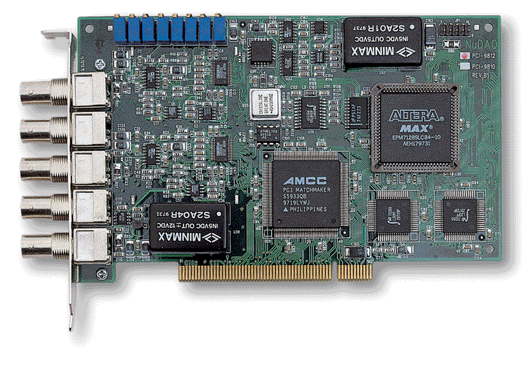
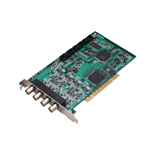
ATUH-16(PCI)
LOOKING FOR THE RIGHT
INDUSTRIAL SOLUTION?
Discover embedded, communication and automation solutions tailored to your application.
- High‑Speed A/D Conversion:
1 µs per channel (1 MS/s) 12‑bit analog‑to‑digital conversion for real‑time, high‑frequency signal capture.
- Flexible Input Configuration:
16 single‑ended or 8 differential analog input channels selectable via onboard jumpers.
- Wide Input Voltage Ranges:
Bipolar ±2.5 V, ±5 V, ±10 V or unipolar 0–5 V, 0–10 V ranges (jumper‑selectable).
- Large Onboard Memory:
16 M‑sample FIFO or ring buffer memory for continuous or cyclic sampling independent of host CPU load.
- Analog Output Channel:
One 12‑bit D/A output channel, ±10 V/±5 V/0–10 V range, 6 µs conversion speed, ±5 mA drive capability.
- Digital I/O:
Four TTL‑level digital inputs and four TTL‑level digital outputs, configurable for counter control or general I/O.
- Programmable Counter:
i8254‑compatible 16‑bit × 3 counter with internal 4 MHz clock or external signal input.
- Comprehensive Triggering:
Supports software, external TTL trigger, or analog level comparison for start/stop control.
- Software & OS Support:
Windows (API‑AIO(WDM), API‑AIO(98/PC)), Linux (API‑AIO(LNX)), and data logging via C‑LOGGER.
Compatible with MATLAB (ML‑DAQ) and LabVIEW (VI‑DAQ) through dedicated plug‑ins.
- High‑Capacity Data Handling:
Background sampling and event‑driven acquisition with overflow detection and status monitoring.
- Compact PCI Short‑Size Form Factor:
176.41 mm (L) × 105.68 mm (H) board fits standard PCI slots (5 V/3.3 V universal key).
- Optional Expansion:
Channel expansion to 32 inputs, simultaneous sampling, isolation, filtering, and terminal accessories available.
1 µs per channel (1 MS/s) 12‑bit analog‑to‑digital conversion for real‑time, high‑frequency signal capture.
- Flexible Input Configuration:
16 single‑ended or 8 differential analog input channels selectable via onboard jumpers.
- Wide Input Voltage Ranges:
Bipolar ±2.5 V, ±5 V, ±10 V or unipolar 0–5 V, 0–10 V ranges (jumper‑selectable).
- Large Onboard Memory:
16 M‑sample FIFO or ring buffer memory for continuous or cyclic sampling independent of host CPU load.
- Analog Output Channel:
One 12‑bit D/A output channel, ±10 V/±5 V/0–10 V range, 6 µs conversion speed, ±5 mA drive capability.
- Digital I/O:
Four TTL‑level digital inputs and four TTL‑level digital outputs, configurable for counter control or general I/O.
- Programmable Counter:
i8254‑compatible 16‑bit × 3 counter with internal 4 MHz clock or external signal input.
- Comprehensive Triggering:
Supports software, external TTL trigger, or analog level comparison for start/stop control.
- Software & OS Support:
Windows (API‑AIO(WDM), API‑AIO(98/PC)), Linux (API‑AIO(LNX)), and data logging via C‑LOGGER.
Compatible with MATLAB (ML‑DAQ) and LabVIEW (VI‑DAQ) through dedicated plug‑ins.
- High‑Capacity Data Handling:
Background sampling and event‑driven acquisition with overflow detection and status monitoring.
- Compact PCI Short‑Size Form Factor:
176.41 mm (L) × 105.68 mm (H) board fits standard PCI slots (5 V/3.3 V universal key).
- Optional Expansion:
Channel expansion to 32 inputs, simultaneous sampling, isolation, filtering, and terminal accessories available.
Comprehensive Product Summary – CONTEC AD12‑16U(PCI)EV
### 1. Product Overview
Product Name: PCI Analog‑to‑Digital Conversion Board
Model: AD12‑16U(PCI)EV
Series: EV Series (High‑Speed & Resolution Analog Input Boards for PCI)
Article Number: AD12‑16U(PCI)EV
Manufacturer: CONTEC CO., LTD., Osaka, Japan
Product Type: High‑speed, high‑resolution PCI analog input/output interface board designed for data acquisition, measurement, and control applications.
Product Category: PCI Bus Analog I/O Board (A/D, D/A, Digital I/O, Counter)
The AD12‑16U(PCI)EV is part of CONTEC’s EV‑series PCI analog input boards, offering 12‑bit resolution and 1 µs per‑channel conversion speed. It provides 16 analog input channels (single‑ended) or 8 differential channels, one analog output channel, four digital inputs, four digital outputs, and a programmable counter. The board is optimized for high‑speed data acquisition and control in Windows or Linux environments, with comprehensive driver and software support.
### 2. Key Features
- High‑Speed A/D Conversion:
1 µs per channel (1 MS/s) 12‑bit analog‑to‑digital conversion for real‑time, high‑frequency signal capture.
- Flexible Input Configuration:
16 single‑ended or 8 differential analog input channels selectable via onboard jumpers.
- Wide Input Voltage Ranges:
Bipolar ±2.5 V, ±5 V, ±10 V or unipolar 0–5 V, 0–10 V ranges (jumper‑selectable).
- Large Onboard Memory:
16 M‑sample FIFO or ring buffer memory for continuous or cyclic sampling independent of host CPU load.
- Analog Output Channel:
One 12‑bit D/A output channel, ±10 V/±5 V/0–10 V range, 6 µs conversion speed, ±5 mA drive capability.
- Digital I/O:
Four TTL‑level digital inputs and four TTL‑level digital outputs, configurable for counter control or general I/O.
- Programmable Counter:
i8254‑compatible 16‑bit × 3 counter with internal 4 MHz clock or external signal input.
- Comprehensive Triggering:
Supports software, external TTL trigger, or analog level comparison for start/stop control.
- Software & OS Support:
Windows (API‑AIO(WDM), API‑AIO(98/PC)), Linux (API‑AIO(LNX)), and data logging via C‑LOGGER.
Compatible with MATLAB (ML‑DAQ) and LabVIEW (VI‑DAQ) through dedicated plug‑ins.
- High‑Capacity Data Handling:
Background sampling and event‑driven acquisition with overflow detection and status monitoring.
- Compact PCI Short‑Size Form Factor:
176.41 mm (L) × 105.68 mm (H) board fits standard PCI slots (5 V/3.3 V universal key).
- Optional Expansion:
Channel expansion to 32 inputs, simultaneous sampling, isolation, filtering, and terminal accessories available.
### 3. Technical Specifications
Analog Input Section
- Type: Non‑isolated, single‑ended or differential (jumper‑selectable)
- Channels: 16 (SE) / 8 (DIFF)
- Input Ranges: ±10 V, ±5 V, ±2.5 V, 0–5 V, 0–10 V (jumper‑selectable)
- Input Impedance: ≥ 1 MΩ
- Absolute Max Input Voltage: ±15 V
- Resolution: 12 bits (4096 steps)
- Non‑linearity Error: ±3 LSB typical
- Conversion Speed: 1 µs per channel (max)
- Input Gain: ×1, ×2, ×4, ×8 (software‑selectable)
- Buffer Memory: 16 M‑sample FIFO or ring buffer
- Trigger Sources: Software, analog level comparison, or external TTL signal
- Stop Conditions: Sampling count, level comparison, external trigger, or software abort
Analog Output Section
- Channels: 1 channel (non‑isolated)
- Output Ranges: ±10 V, ±5 V, 0–10 V (jumper‑selectable)
- Resolution: 12 bits
- Conversion Speed: 6 µs (max)
- Output Current: ±5 mA
- Output Impedance: ≤ 1 Ω
- Non‑linearity Error: ±½ LSB
Digital I/O Section
- Digital Inputs: 4 channels, TTL level
- Digital Outputs: 4 channels, TTL level
- Shared Functions: Counter gate/clock/output selectable via jumpers
- Input Threshold: TTL compatible
- Output Drive: 24 mA (sink/source)
Counter Section
- Device: i8254‑compatible, 3 × 16‑bit counters
- Clock Source: Internal 4 MHz or external TTL input
- Modes: Programmable one‑shot, rate generator, event counting
- External Connections: CNT Clock, CNT Gate, CNT Output via CN2
Electrical & Mechanical
- Bus Interface: PCI 32‑bit, 33 MHz, universal key (3.3 V/5 V)
- Power Requirement: +5 V ± 5 %, 1000 mA (max)
- Dimensions: 176.41 mm (L) × 105.68 mm (H)
- Weight: Approx. 150 g
- Operating Temperature: 0 – 50 °C
- Operating Humidity: 10 – 90 % RH (non‑condensing)
- Storage: Avoid direct sunlight, moisture, vibration, static, or magnetic fields
Connectors
- CN1: 37‑pin D‑SUB female (analog I/O)
- CN2: 16‑pin pin‑header (digital I/O, counter, control)
- CN3: Expansion connector for ATUH‑16A(PCI) sub‑board
### 4. Functionality
Operation Principle:
The AD12‑16U(PCI)EV performs high‑speed analog‑to‑digital conversion of voltage signals and transfers digitized data to onboard memory. Sampling can be continuous (FIFO) or cyclic (ring). The board supports both software‑controlled and hardware‑triggered acquisition, enabling precise synchronization with external events.
Use Cases & Applications:
- Industrial measurement and control
- Data logging and waveform capture
- Laboratory instrumentation
- Process monitoring and automation
- Signal analysis and test systems
- Integration with MATLAB/LabVIEW for research and development
Compatibility:
- Operating Systems: Windows 7/Vista/XP/Server 2003, Linux (Red Hat, TurboLinux)
- Programming Languages: Visual C++, C#, VB, Delphi, C++ Builder, gcc
- Software Integration: C‑LOGGER, MATLAB (ML‑DAQ), LabVIEW (VI‑DAQ)
### 5. Components & Accessories
Standard Package Contents:
- AD12‑16U(PCI)EV board (1 pc)
- First Step Guide (1 pc)
- CD‑ROM (API‑PAC(W32)) containing drivers, utilities, and manuals
- Warranty Certificate (3‑year limited)
- Serial Number Label
Optional Cables:
- PCA37P‑1.5 (1.5 m flat cable, 37‑pin D‑SUB)
- PCA37PS‑0.5P / 1.5P (shielded 37‑pin D‑SUB)
- PCB37PS‑0.5P / 1.5P (shielded 37‑pin both ends)
- PCC16PS‑1.5 / 3 (coaxial for single‑ended inputs)
- PCD8PS‑1.5 / 3 (2‑wire shielded for differential inputs)
- DT/E1 (16‑pin header cable 1.5 m)
- DT‑E3 (16‑pin to 15‑pin conversion cable with bracket)
Optional Accessories:
- ATP‑16E (BNC terminal unit 16 ch)
- ATBA‑16E (Buffer amplifier box 16 ch)
- EPD‑37 / EPD‑37A (Screw terminal units)
- DTP‑3C / DTP‑4C (General purpose terminal boards)
- ATSS‑16 / ATSS‑16A (Simultaneous sample & hold units)
- ATII‑8C (Isolated input expansion board 8 ch)
- ATLF‑8A (Gain amplifier board 8 ch)
- ATUH‑16A(PCI) (16 ch multiplexer sub‑board for U‑series)
### 6. Installation & Setup
System Requirements:
- Available PCI 32‑bit slot (5 V or 3.3 V)
- +5 V power supply ≥ 1 A
- Administrator privileges for driver installation
Installation Steps:
1. Install Software:
Run the API‑PAC(W32) installer from the CD‑ROM before inserting the board.
Choose API‑AIO(WDM) for modern Windows or API‑AIO(98/PC) for legacy systems.
2. Configure Hardware:
Set jumpers for input/output ranges, input mode (SE/DIFF), and counter configuration.
Assign a unique Board ID (0–Fh) if multiple boards are installed.
3. Insert Board:
Power off the PC, insert the board into a PCI slot, and secure with a screw.
4. Driver Installation:
Upon reboot, the OS detects the board. Point the hardware wizard to the INF directory on the CD‑ROM.
5. Initialization:
Configure device name and parameters via Device Manager (WDM) or API‑TOOL Configuration (98/PC).
6. Verification:
Use the built‑in Diagnosis Program to test analog input/output, digital I/O, and counter functions.
Mounting Options:
Standard PCI short‑size board; fits desktop or industrial PCs.
### 7. Performance & Capabilities
- Sampling Rate: 1 MS/s (1 µs per channel)
- Resolution: 12 bits (0.00244 V per step at 10 V range)
- Analog Output Speed: 6 µs per conversion
- Memory Capacity: 16 M samples (FIFO or ring)
- Digital I/O: 4 input + 4 output TTL channels
- Counter: 3 × 16‑bit (i8254 equivalent)
- Accuracy: ±3 LSB non‑linearity typical
- Operating Range: 0–50 °C, 10–90 % RH
- Power Consumption: +5 V @ 1000 mA max
- Limitations: Non‑isolated I/O; input voltage must not exceed ±15 V relative to AGND.
### 8. Standards & Compliance
- Bus Standard: PCI Rev. 2.2 (32‑bit, 33 MHz, universal key)
- Signal Levels: TTL compatible digital I/O
- Environmental: 0–50 °C operation, 10–90 % RH non‑condensing
- Safety & Quality: Manufactured under CONTEC quality standards; calibrated before shipment
- Regulatory: Designed for industrial and laboratory use in compliance with applicable EMC and safety requirements
### 9. Additional Information
Warranty:
Limited three‑year warranty against defects in materials and workmanship.
Covers electronic circuitry only; excludes damage from misuse or modification.
Support & Service:
- Website: [https://www.contec.com](https://www.contec.com)
- Downloads: Drivers, utilities, sample programs, and manuals available free of charge.
- RMA Procedure: Obtain Return Merchandise Authorization before sending for repair.
Maintenance:
- Periodically inspect connectors for dust or corrosion.
- Clean edge contacts with industrial alcohol if touched.
- Store in anti‑static bag away from moisture and magnetic fields.
Calibration:
Factory‑calibrated prior to shipment; contact CONTEC for re‑calibration if performance degrades.
Software Updates:
Updated drivers and utilities available online (API‑PAC, C‑LOGGER, VI‑DAQ, ML‑DAQ).
Documentation:
Comprehensive User’s Guide (PDF) included on CD‑ROM and available for download.
### Summary
The CONTEC AD12‑16U(PCI)EV is a high‑speed, 12‑bit PCI analog input/output board engineered for precision data acquisition and control. With 16 analog inputs, 1 analog output, 4 digital inputs, 4 digital outputs, and a programmable counter, it delivers 1 MS/s sampling performance and 16 M‑sample buffer capacity. Its broad input range options, software triggering, and comprehensive driver support make it ideal for industrial measurement, scientific research, and automation applications. The board is fully supported under Windows and Linux environments and integrates seamlessly with MATLAB and LabVIEW for advanced data analysis and control solutions.

### 1. Product Overview
Product Name: PCI Analog‑to‑Digital Conversion Board
Model: AD12‑16U(PCI)EV
Series: EV Series (High‑Speed & Resolution Analog Input Boards for PCI)
Article Number: AD12‑16U(PCI)EV
Manufacturer: CONTEC CO., LTD., Osaka, Japan
Product Type: High‑speed, high‑resolution PCI analog input/output interface board designed for data acquisition, measurement, and control applications.
Product Category: PCI Bus Analog I/O Board (A/D, D/A, Digital I/O, Counter)
The AD12‑16U(PCI)EV is part of CONTEC’s EV‑series PCI analog input boards, offering 12‑bit resolution and 1 µs per‑channel conversion speed. It provides 16 analog input channels (single‑ended) or 8 differential channels, one analog output channel, four digital inputs, four digital outputs, and a programmable counter. The board is optimized for high‑speed data acquisition and control in Windows or Linux environments, with comprehensive driver and software support.
### 2. Key Features
- High‑Speed A/D Conversion:
1 µs per channel (1 MS/s) 12‑bit analog‑to‑digital conversion for real‑time, high‑frequency signal capture.
- Flexible Input Configuration:
16 single‑ended or 8 differential analog input channels selectable via onboard jumpers.
- Wide Input Voltage Ranges:
Bipolar ±2.5 V, ±5 V, ±10 V or unipolar 0–5 V, 0–10 V ranges (jumper‑selectable).
- Large Onboard Memory:
16 M‑sample FIFO or ring buffer memory for continuous or cyclic sampling independent of host CPU load.
- Analog Output Channel:
One 12‑bit D/A output channel, ±10 V/±5 V/0–10 V range, 6 µs conversion speed, ±5 mA drive capability.
- Digital I/O:
Four TTL‑level digital inputs and four TTL‑level digital outputs, configurable for counter control or general I/O.
- Programmable Counter:
i8254‑compatible 16‑bit × 3 counter with internal 4 MHz clock or external signal input.
- Comprehensive Triggering:
Supports software, external TTL trigger, or analog level comparison for start/stop control.
- Software & OS Support:
Windows (API‑AIO(WDM), API‑AIO(98/PC)), Linux (API‑AIO(LNX)), and data logging via C‑LOGGER.
Compatible with MATLAB (ML‑DAQ) and LabVIEW (VI‑DAQ) through dedicated plug‑ins.
- High‑Capacity Data Handling:
Background sampling and event‑driven acquisition with overflow detection and status monitoring.
- Compact PCI Short‑Size Form Factor:
176.41 mm (L) × 105.68 mm (H) board fits standard PCI slots (5 V/3.3 V universal key).
- Optional Expansion:
Channel expansion to 32 inputs, simultaneous sampling, isolation, filtering, and terminal accessories available.
### 3. Technical Specifications
Analog Input Section
- Type: Non‑isolated, single‑ended or differential (jumper‑selectable)
- Channels: 16 (SE) / 8 (DIFF)
- Input Ranges: ±10 V, ±5 V, ±2.5 V, 0–5 V, 0–10 V (jumper‑selectable)
- Input Impedance: ≥ 1 MΩ
- Absolute Max Input Voltage: ±15 V
- Resolution: 12 bits (4096 steps)
- Non‑linearity Error: ±3 LSB typical
- Conversion Speed: 1 µs per channel (max)
- Input Gain: ×1, ×2, ×4, ×8 (software‑selectable)
- Buffer Memory: 16 M‑sample FIFO or ring buffer
- Trigger Sources: Software, analog level comparison, or external TTL signal
- Stop Conditions: Sampling count, level comparison, external trigger, or software abort
Analog Output Section
- Channels: 1 channel (non‑isolated)
- Output Ranges: ±10 V, ±5 V, 0–10 V (jumper‑selectable)
- Resolution: 12 bits
- Conversion Speed: 6 µs (max)
- Output Current: ±5 mA
- Output Impedance: ≤ 1 Ω
- Non‑linearity Error: ±½ LSB
Digital I/O Section
- Digital Inputs: 4 channels, TTL level
- Digital Outputs: 4 channels, TTL level
- Shared Functions: Counter gate/clock/output selectable via jumpers
- Input Threshold: TTL compatible
- Output Drive: 24 mA (sink/source)
Counter Section
- Device: i8254‑compatible, 3 × 16‑bit counters
- Clock Source: Internal 4 MHz or external TTL input
- Modes: Programmable one‑shot, rate generator, event counting
- External Connections: CNT Clock, CNT Gate, CNT Output via CN2
Electrical & Mechanical
- Bus Interface: PCI 32‑bit, 33 MHz, universal key (3.3 V/5 V)
- Power Requirement: +5 V ± 5 %, 1000 mA (max)
- Dimensions: 176.41 mm (L) × 105.68 mm (H)
- Weight: Approx. 150 g
- Operating Temperature: 0 – 50 °C
- Operating Humidity: 10 – 90 % RH (non‑condensing)
- Storage: Avoid direct sunlight, moisture, vibration, static, or magnetic fields
Connectors
- CN1: 37‑pin D‑SUB female (analog I/O)
- CN2: 16‑pin pin‑header (digital I/O, counter, control)
- CN3: Expansion connector for ATUH‑16A(PCI) sub‑board
### 4. Functionality
Operation Principle:
The AD12‑16U(PCI)EV performs high‑speed analog‑to‑digital conversion of voltage signals and transfers digitized data to onboard memory. Sampling can be continuous (FIFO) or cyclic (ring). The board supports both software‑controlled and hardware‑triggered acquisition, enabling precise synchronization with external events.
Use Cases & Applications:
- Industrial measurement and control
- Data logging and waveform capture
- Laboratory instrumentation
- Process monitoring and automation
- Signal analysis and test systems
- Integration with MATLAB/LabVIEW for research and development
Compatibility:
- Operating Systems: Windows 7/Vista/XP/Server 2003, Linux (Red Hat, TurboLinux)
- Programming Languages: Visual C++, C#, VB, Delphi, C++ Builder, gcc
- Software Integration: C‑LOGGER, MATLAB (ML‑DAQ), LabVIEW (VI‑DAQ)
### 5. Components & Accessories
Standard Package Contents:
- AD12‑16U(PCI)EV board (1 pc)
- First Step Guide (1 pc)
- CD‑ROM (API‑PAC(W32)) containing drivers, utilities, and manuals
- Warranty Certificate (3‑year limited)
- Serial Number Label
Optional Cables:
- PCA37P‑1.5 (1.5 m flat cable, 37‑pin D‑SUB)
- PCA37PS‑0.5P / 1.5P (shielded 37‑pin D‑SUB)
- PCB37PS‑0.5P / 1.5P (shielded 37‑pin both ends)
- PCC16PS‑1.5 / 3 (coaxial for single‑ended inputs)
- PCD8PS‑1.5 / 3 (2‑wire shielded for differential inputs)
- DT/E1 (16‑pin header cable 1.5 m)
- DT‑E3 (16‑pin to 15‑pin conversion cable with bracket)
Optional Accessories:
- ATP‑16E (BNC terminal unit 16 ch)
- ATBA‑16E (Buffer amplifier box 16 ch)
- EPD‑37 / EPD‑37A (Screw terminal units)
- DTP‑3C / DTP‑4C (General purpose terminal boards)
- ATSS‑16 / ATSS‑16A (Simultaneous sample & hold units)
- ATII‑8C (Isolated input expansion board 8 ch)
- ATLF‑8A (Gain amplifier board 8 ch)
- ATUH‑16A(PCI) (16 ch multiplexer sub‑board for U‑series)
### 6. Installation & Setup
System Requirements:
- Available PCI 32‑bit slot (5 V or 3.3 V)
- +5 V power supply ≥ 1 A
- Administrator privileges for driver installation
Installation Steps:
1. Install Software:
Run the API‑PAC(W32) installer from the CD‑ROM before inserting the board.
Choose API‑AIO(WDM) for modern Windows or API‑AIO(98/PC) for legacy systems.
2. Configure Hardware:
Set jumpers for input/output ranges, input mode (SE/DIFF), and counter configuration.
Assign a unique Board ID (0–Fh) if multiple boards are installed.
3. Insert Board:
Power off the PC, insert the board into a PCI slot, and secure with a screw.
4. Driver Installation:
Upon reboot, the OS detects the board. Point the hardware wizard to the INF directory on the CD‑ROM.
5. Initialization:
Configure device name and parameters via Device Manager (WDM) or API‑TOOL Configuration (98/PC).
6. Verification:
Use the built‑in Diagnosis Program to test analog input/output, digital I/O, and counter functions.
Mounting Options:
Standard PCI short‑size board; fits desktop or industrial PCs.
### 7. Performance & Capabilities
- Sampling Rate: 1 MS/s (1 µs per channel)
- Resolution: 12 bits (0.00244 V per step at 10 V range)
- Analog Output Speed: 6 µs per conversion
- Memory Capacity: 16 M samples (FIFO or ring)
- Digital I/O: 4 input + 4 output TTL channels
- Counter: 3 × 16‑bit (i8254 equivalent)
- Accuracy: ±3 LSB non‑linearity typical
- Operating Range: 0–50 °C, 10–90 % RH
- Power Consumption: +5 V @ 1000 mA max
- Limitations: Non‑isolated I/O; input voltage must not exceed ±15 V relative to AGND.
### 8. Standards & Compliance
- Bus Standard: PCI Rev. 2.2 (32‑bit, 33 MHz, universal key)
- Signal Levels: TTL compatible digital I/O
- Environmental: 0–50 °C operation, 10–90 % RH non‑condensing
- Safety & Quality: Manufactured under CONTEC quality standards; calibrated before shipment
- Regulatory: Designed for industrial and laboratory use in compliance with applicable EMC and safety requirements
### 9. Additional Information
Warranty:
Limited three‑year warranty against defects in materials and workmanship.
Covers electronic circuitry only; excludes damage from misuse or modification.
Support & Service:
- Website: [https://www.contec.com](https://www.contec.com)
- Downloads: Drivers, utilities, sample programs, and manuals available free of charge.
- RMA Procedure: Obtain Return Merchandise Authorization before sending for repair.
Maintenance:
- Periodically inspect connectors for dust or corrosion.
- Clean edge contacts with industrial alcohol if touched.
- Store in anti‑static bag away from moisture and magnetic fields.
Calibration:
Factory‑calibrated prior to shipment; contact CONTEC for re‑calibration if performance degrades.
Software Updates:
Updated drivers and utilities available online (API‑PAC, C‑LOGGER, VI‑DAQ, ML‑DAQ).
Documentation:
Comprehensive User’s Guide (PDF) included on CD‑ROM and available for download.
### Summary
The CONTEC AD12‑16U(PCI)EV is a high‑speed, 12‑bit PCI analog input/output board engineered for precision data acquisition and control. With 16 analog inputs, 1 analog output, 4 digital inputs, 4 digital outputs, and a programmable counter, it delivers 1 MS/s sampling performance and 16 M‑sample buffer capacity. Its broad input range options, software triggering, and comprehensive driver support make it ideal for industrial measurement, scientific research, and automation applications. The board is fully supported under Windows and Linux environments and integrates seamlessly with MATLAB and LabVIEW for advanced data analysis and control solutions.
-
ContecCatalog2011-2012-en-G Analog IO.pdf
PDF Catalog
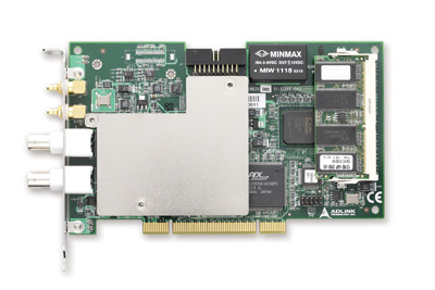
- ATUH-16(PCI) - Extra inputs 32SE/16DI for AD12-16U(PCI)-series
- ATII-8A - Isolated 8 differential inputs panel
- ATSS-16 - Sample & hold panel for 16 single ended inputs
- ATLF-8 - 8 channel signal conditioning panel
- ATP-16 - 16 BNC channel single ended, D-sub 37f
- DTP-3C - General purpose screw terminal panel, 2*22 large screw
- DTP-4C - General purpose M2.5 screw terminal panel, 4*10 screw blocks
- EPD-37A - DIN-rail mountable unit with DB-37f