Comprehensive Product Summary: ADLINK ACL‑8113A Isolated Analog Input Card
### 1. Product Overview
Product Name: ACL‑8113A
Article Number: ACL‑8113A
Series: NuDAQ ISA‑Bus Data Acquisition Series
Model Description: AT A/D Card, 32 Single‑Ended Isolated Channels, 50 kS/s, 12‑bit Resolution
Manufacturer: ADLINK Technology Inc.
Manufacturer Address: 9F, No. 166, Jian Yi Road, Chungho City, Taipei 235, Taiwan, R.O.C.
Website: [www.adlink.com.tw](http://www.adlink.com.tw)
Support Contacts:
- Sales & Service: service@adlink.com.tw
- Technical Support (NuDAQ): nudaq@adlink.com.tw
- Software Support: sw@adlink.com.tw
Product Category: Industrial Data Acquisition (DAQ) Hardware for ISA Bus Systems
Manual Revision: Rev. 2.15, May 31, 2000
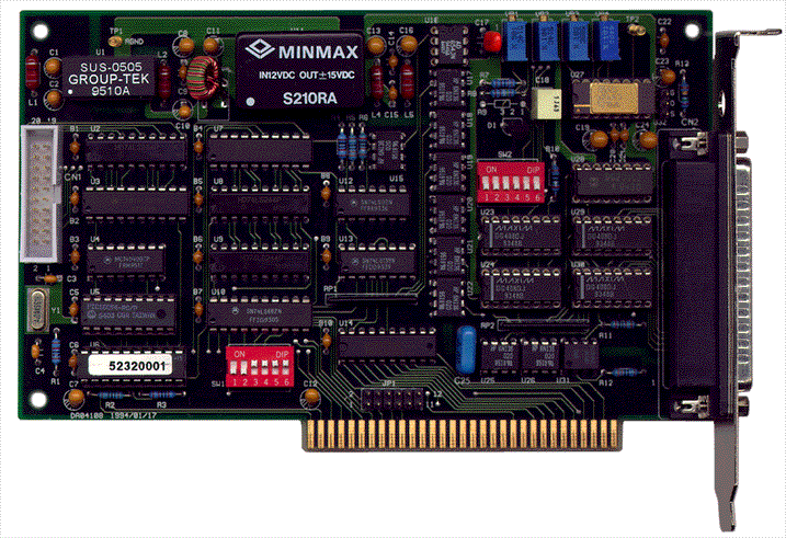
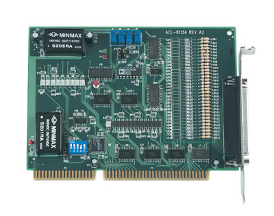
The ADLINK ACL‑8113A is a 12‑bit, 32‑channel, single‑ended isolated analog input card designed for ISA‑bus PCs. It provides high‑voltage isolation, programmable gain, and on‑board signal conditioning for industrial measurement, monitoring, and control applications.
### 2. Key Features
- 32 Single‑Ended Analog Input Channels: Each channel is individually isolated to protect the host PC and peripherals from high‑voltage transients.
- High Isolation Voltage: Over 2500 VDC channel‑to‑system isolation ensures robust protection in noisy or high‑voltage environments.
- 12‑bit Resolution: Utilizes a Burr‑Brown AD574 or equivalent successive‑approximation A/D converter for precise analog‑to‑digital conversion.
- Sampling Rate: Up to 50 kHz (50 kS/s) maximum conversion speed.
- Programmable Input Range:
- 10 V Range: Bipolar ±0.3125 V – ±5 V; Unipolar 0–0.625 V – 0–10 V
- 20 V Range: Bipolar ±0.625 V – ±10 V; Unipolar 0–1.25 V – 0–10 V
- Software‑Programmable Gain: Selectable gains of ×1, ×2, ×4, ×8, ×16 per channel.
- Integrated DC‑to‑DC Converters: Provide stable isolated power for analog circuitry.
- Compact Half‑Size ISA Card: 4‑layer PCB with integral ground plane for noise immunity.
- On‑Board Signal Conditioning: RC filter networks per channel for attenuation or current‑to‑voltage conversion.
- Over‑Voltage Protection: Continuous ±35 V maximum input protection.
- Software Triggered Conversion: Fully software‑controlled A/D triggering and data acquisition.
- Comprehensive Software Support: DOS C/C++ libraries, Windows DLLs, and LabVIEW drivers.
- Calibration Adjustments: Four precision trimmers (VR1–VR4) for offset and full‑scale calibration in bipolar and unipolar modes.
### 3. Technical Specifications
Analog Input Section
- Channels: 32 isolated single‑ended (SE) inputs
- Resolution: 12 bits
- Input Ranges:
- *10 V Range*
- Bipolar: ±5 V, ±2.5 V, ±1.25 V, ±0.625 V, ±0.3125 V
- Unipolar: 0–10 V, 0–5 V, 0–2.5 V, 0–1.25 V, 0–0.625 V
- *20 V Range*
- Bipolar: ±10 V, ±5 V, ±2.5 V, ±1.25 V, ±0.625 V
- Unipolar: 0–10 V, 0–5 V, 0–2.5 V, 0–1.25 V
- Input Impedance: 10 MΩ typical
- Isolation Voltage: > 2500 VDC channel‑to‑system
- Over‑Voltage Protection: ±35 V continuous
- A/D Converter Type: Successive Approximation (AD574 or equivalent)
- Conversion Rate: 50 kHz maximum
- Accuracy: ±0.015 % of reading ± 1 LSB
- Non‑Linearity: ±1 bit maximum
- Temperature Coefficient: 5 ppm typical, 15 ppm maximum
- Trigger Mode: Software trigger only
- Data Transfer: Program‑controlled (polling)
General Specifications
- Connector: 37‑pin D‑type female (DB‑37)
- Power Requirement: +5 V DC @ 960 mA max
- Dimensions: 160 mm (L) × 122 mm (W)
- Operating Temperature: 0 °C – 55 °C
- Storage Temperature: −20 °C – 80 °C
- Humidity: 5 – 95 % RH, non‑condensing
- PCB Type: 4‑layer with ground plane
- Form Factor: Half‑size ISA card
### 4. Functionality
The ACL‑8113A performs analog‑to‑digital conversion on up to 32 isolated single‑ended channels. Each channel’s input passes through an RC conditioning network and isolation barrier before reaching the multiplexer and A/D converter. The card supports both bipolar and unipolar input modes, selectable via jumpers (JP1, JP2) and software‑controlled gain settings.
Operation Sequence:
1. Select input channel via channel control register (Base + 10).
2. Configure gain and range via range control register (Base + 9).
3. Initiate conversion by writing to the software trigger register (Base + 12).
4. Poll the DRDY bit (Base + 5) until conversion completes.
5. Read 12‑bit result from data registers (Base + 4 and Base + 5).
Applications:
- Industrial process monitoring and control
- Multi‑channel sensor and transducer measurement
- Waveform acquisition and transient analysis
- Vibration and condition monitoring
- General laboratory data acquisition
- Signal isolation and noise‑sensitive measurement environments
Compatibility:
- ISA‑bus PCs (16‑bit slot)
- Supported operating systems: DOS, Windows 3.1/95/98/NT (via ACLS‑DLL2)
- Supported software: Borland C/C++, Microsoft C, Visual C++, Visual Basic, Delphi, LabVIEW
### 5. Components & Accessories
Package Contents:
- ACL‑8113A 32‑Channel Isolated A/D Card
- ADLINK CD containing:
- DOS C/C++ library and utilities
- ACLS‑DLL2 Windows development kit (licensed)
- ACLS‑LVIEW LabVIEW driver package (licensed)
- Calibration program and documentation
- Printed User’s Manual
Connectors:
- DB‑37 Female Connector Pinout:
- Pins 1–32: AI0–AI31 (Analog Input Channels 0–31)
- Pins 9, 10, 19, 20, 29, 30, 37: Analog Ground (A.GND)
Optional Accessories:
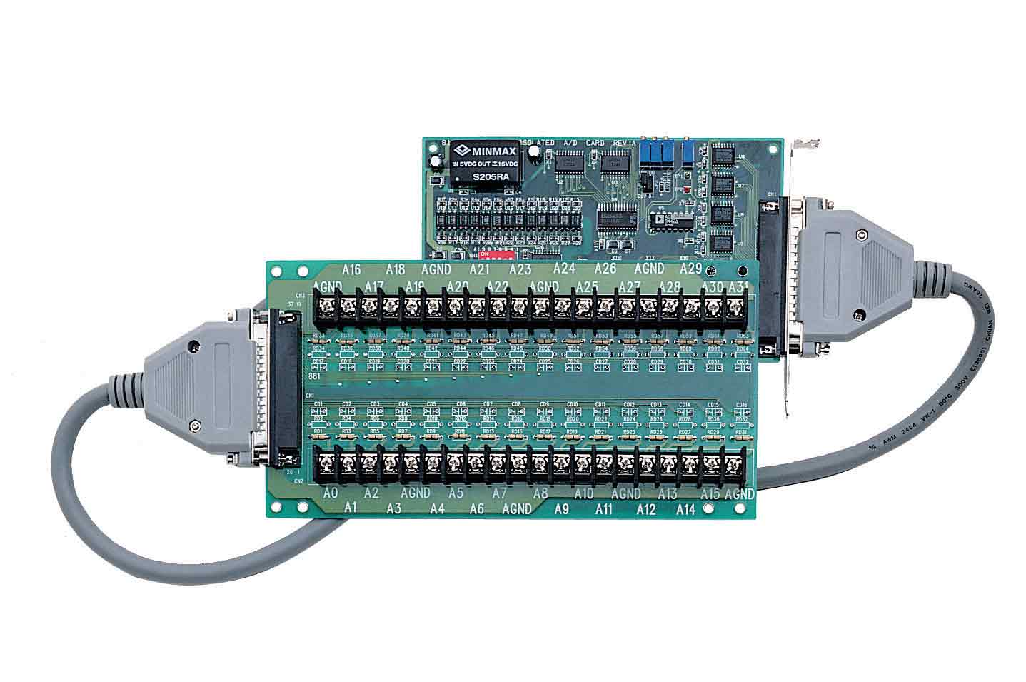
- Shielded DB‑37 cable assemblies
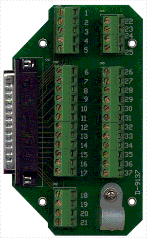
- Terminal boards for signal wiring
- External calibration and test fixtures
### 6. Installation & Setup
System Requirements:
- IBM‑PC/AT or compatible with available ISA slot
- +5 V DC power supply capable of 1 A
- Operating environment within 0–55 °C
Installation Steps:
1. Unpacking: Handle the card on a grounded anti‑static mat using an ESD wrist strap. Inspect for shipping damage.
2. Base Address Configuration:
- Selectable via 5‑position DIP switch (SW1).
- Default base address: 0x220.
- Requires 16 consecutive I/O addresses (000h–3F0h range).
3. Input Range Selection:
- JP1: Selects voltage range (10 V / 20 V).
- JP2: Selects polarity (Bipolar / Unipolar).
4. Mounting: Insert card into ISA slot, secure bracket, and connect DB‑37 cable.
5. Software Installation:
- For DOS: run `SETUP` from CD directory `\NuDAQISA\8113`.
- For Windows: install ACLS‑DLL2 or ACLS‑LVIEW from CD.
6. Calibration: Use provided calibration program and precision instruments to adjust VR1–VR4 for offset and full‑scale accuracy.
Jumper Summary:
- JP1: 10 V (default) / 20 V range
- JP2: UN (Unipolar) / BI (Bipolar default)
### 7. Performance & Capabilities
Conversion Performance:
- Maximum throughput: 50 k samples per second
- Resolution: 12 bits (4096 discrete levels)
- Accuracy: ±0.015 % of reading ± 1 LSB
- Non‑linearity: ±1 bit
- Input impedance: 10 MΩ ensures minimal loading
- Temperature drift: ≤ 15 ppm max
Gain and Range Control:
- Software‑selectable gains (×1 – ×16) allow optimization of resolution for varying signal amplitudes.
- Bipolar and unipolar modes accommodate both AC‑coupled and DC‑referenced sensors.
Data Handling:
- Conversion results stored in two 8‑bit registers (low/high byte).
- DRDY flag indicates conversion completion.
- Data range: 0–4095 (12‑bit).
Example Voltage Mapping (Gain = 1):
| Mode | Input Range | Digital Output Range | Example |
|------|--------------|----------------------|----------|
| Bipolar ±10 V | −10 V → 0 → +10 V | 0 → 2048 → 4095 | 0 V ≈ 2048 counts |
| Bipolar ±5 V | −5 V → 0 → +5 V | 0 → 2048 → 4095 | 0 V ≈ 2048 counts |
| Unipolar 0–10 V | 0 → 10 V | 0 → 4095 | 5 V ≈ 2048 counts |
Limitations:
- Software‑triggered only (no hardware or external trigger).
- Program‑controlled data transfer (no DMA).
- Single‑ended inputs only (no differential mode).
### 8. Standards & Compliance
- Isolation Rating: > 2500 VDC channel‑to‑system
- Over‑Voltage Protection: ±35 V continuous
- Environmental: 0–55 °C operating, −20–80 °C storage, 5–95 % RH non‑condensing
- Electrical Safety: Designed for industrial measurement environments with galvanic isolation
- EMC Considerations: 4‑layer PCB with ground plane minimizes noise coupling
- Software Standards: Compatible with standard C/C++ compilers and LabVIEW VIs
- Regulatory Compliance: Conforms to ADLINK internal quality and reliability standards for ISA‑bus DAQ hardware
### 9. Additional Information
Calibration Details:
- VR1: A/D bipolar offset adjustment
- VR2: A/D bipolar full‑scale adjustment
- VR3: Programmable amplifier offset adjustment
- VR4: A/D unipolar full‑scale adjustment
Calibration requires a 6½‑digit multimeter and a precision DC voltage source.
Software Support:
- DOS Library: Six C‑language functions for initialization, channel selection, gain control, and data acquisition (`_8113_Initial`, `_8113_ActCard_Set`, `_8113_Channel_Select`, `_8113_Gain_Select`, `_8113_AD_Acquire`, `_8113_MAD_Acquire`).
- Windows DLL (ACLS‑DLL2): Supports VC++, VB, Delphi under Windows 95/98/NT.
- LabVIEW Driver (ACLS‑LVIEW): Provides VIs for integration with NI LabVIEW.
Warranty:
- Duration: 1 year from confirmed purchase date.
- Coverage: Free from defects in materials and workmanship.
- Exclusions: Damage from misuse, modification, or operation beyond specifications.
- Service Procedure: Return prepaid with proof of purchase; repair or replacement at manufacturer’s discretion.
Maintenance:
- Periodic calibration recommended for precision applications.
- Keep card free from dust and moisture; store in anti‑static packaging when not in use.
Support & Updates:
- Firmware and driver updates available via ADLINK website.
- Technical assistance provided through dedicated NuDAQ support channels.
### Summary
The ADLINK ACL‑8113A is a robust, high‑isolation, 12‑bit analog input card tailored for industrial and laboratory data acquisition on ISA‑bus systems. With 32 isolated single‑ended channels, programmable gain, and flexible input ranges up to ±10 V, it delivers reliable performance for multi‑channel measurement and monitoring tasks. Its integrated DC‑DC converters, software‑controlled configuration, and comprehensive programming libraries make it a versatile and cost‑effective solution for engineers requiring precise, isolated analog data acquisition in legacy PC environments.

 LOOKING FOR THE RIGHT
 A8113 Manual.PDF
Manual
A8113 Manual.PDF
Manual