Comprehensive Product Summary – ADLINK NuDAQ® ACLD‑9138‑01 General‑Purpose Panel
### 1. Product Overview
Product Name: NuDAQ® ACLD‑9138‑01
Model Number: ACLD‑9138‑01
Series: ADLINK NuDAQ® ACLD Series Termination Boards
Article Number: ACLD‑9138‑01
Manufacturer: ADLINK Technology Inc., Taipei, Taiwan, R.O.C.
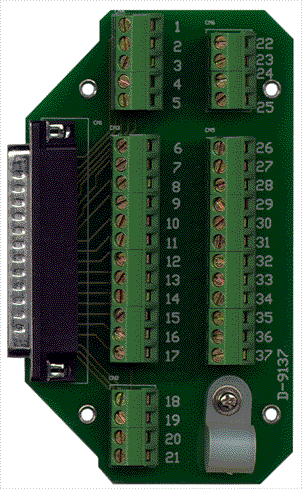
Product Type: General‑purpose termination panel with 37‑pin D‑type connector and dual 20‑pin small screw terminal blocks.
Intended Use: Universal screw‑terminal interface board for signal conditioning and field wiring in data acquisition (DAQ) and control systems.
The ACLD‑9138‑01 is part of ADLINK’s NuDAQ® ACLD family of termination and conditioning boards designed to simplify wiring between PCI/ISA DAQ cards and external sensors or actuators. It provides a convenient, reliable, and configurable interface for analog or digital signals, supporting both laboratory and industrial environments.
### 2. Key Features
- Universal Screw Terminal Interface:
Provides 2×20 small screw terminals for secure, tool‑accessible wiring of field signals.
- 37‑Pin D‑Sub Connector:
Standard female DB‑37 connector for direct connection to ADLINK DAQ cards or external devices.
- 16 Single‑Ended Channels:
Supports 16 single‑ended analog input channels (AI0–AI15) with shared ground reference.
- On‑Board Signal Conditioning Pads:
User‑configurable resistor and capacitor positions (RAx, RBx, Cx) allow implementation of filters, attenuators, or current‑to‑voltage converters.
- Power Status Indicator:
On‑board LED indicates active power supply between DB‑37 pins 15 (+5 V) and 19 (ground).
- Compact, Panel‑Mountable Design:
Includes nylon standoffs for table‑top or panel installation.
- Compatibility:
Designed for use with ADLINK PCI‑9111/9112, ACL‑8112, ACL‑8216, and ACL‑8312/8316 series DAQ cards.
- Ease of Integration:
Two 20‑pin flat‑ribbon connectors simplify connection to host DAQ boards.
- Flexible Signal Conditioning:
Supports user‑defined passive circuits for low‑pass filtering, voltage attenuation, or current‑loop conversion.
- Industrial Reliability:
Screw terminals and plated through‑holes ensure robust mechanical and electrical connections.
### 3. Technical Specifications
| Parameter | Specification |
|----------------|------------------|
| Channels | 16 single‑ended analog input channels |
| Connector Type | 37‑pin D‑Sub female (DB‑37) |
| Terminal Blocks | Dual 20‑pin small screw terminals (2×20) |
| Signal Type | Single‑ended analog or digital I/O |
| Ground Reference | Common ground for all channels |
| Power Indicator | LED between CN1_15 (+5 V) and CN1_19 (GND) |
| Power Supply | +5 V DC from DAQ card via DB‑37 connector |
| Dimensions | Approx. 203 mm × 132 mm (typical ACLD board size) |
| Mounting | Table‑top or panel mounting using nylon standoffs |
| Material | FR‑4 PCB with solder mask and silkscreen labeling |
| Operating Environment | 0 °C to 50 °C, non‑condensing humidity |
| Storage Environment | −20 °C to 70 °C |
| Weight | Approx. 0.3 kg (board only) |
| Cable Compatibility | ACL‑10237‑1 or equivalent 37‑pin D‑Sub cable (not included) |
### 4. Functionality
The ACLD‑9138‑01 serves as a termination and signal conditioning interface between ADLINK DAQ cards and external sensors or control signals. It provides a structured wiring platform that allows users to:
- Connect analog input signals from sensors or transducers to DAQ cards.
- Implement custom passive conditioning circuits (resistors/capacitors) for filtering or scaling.
- Monitor power status via the on‑board LED.
- Simplify maintenance and troubleshooting through labeled screw terminals and accessible layout.
Operating Principle:
Each input channel (AI0–AI15) is routed from the DB‑37 connector to a corresponding screw terminal pair. The board includes resistor pads (RAx, RBx) and capacitor pads (Cx) that can be populated to form RC filters or voltage dividers. All channels share a common ground plane, making the board suitable for single‑ended measurement configurations.
Typical Use Cases:
- Laboratory data acquisition setups requiring quick signal wiring.
- Industrial control panels interfacing analog sensors to PCI DAQ cards.
- Educational or R&D environments for prototyping signal conditioning circuits.
- Integration with ADLINK’s NuDAQ® PCI‑9111/9112 or ACL‑8112/8216 analog input modules.
Compatibility:
Fully compatible with ADLINK’s NuDAQ® and ACL series boards, including:
- PCI‑9112, PCI‑9111 Series
- ACL‑8312 / ACL‑8316
- ACL‑8112 Series
- ACL‑8216
### 5. Components & Accessories
Included Items:
- ACLD‑9138‑01 Industrial Terminal Board
- Two 20‑pin, 1‑meter flat‑ribbon cables
- Nylon standoffs for mounting
- User documentation (electronic/manual)
Optional Accessories:
- ACL‑10237‑1 shielded 37‑pin D‑Sub cable (not included)
- Additional screw terminal blocks or replacement connectors
- External enclosure or DIN‑rail mounting kit (optional, depending on installation)
Connectors:
- CN1: 37‑pin D‑Sub female connector (main interface to DAQ card)
- Screw Terminals: 2×20 small screw terminals for field wiring
- Power LED Circuit: Connected between CN1_15 (+5 V) and CN1_19 (GND)
### 6. Installation & Setup
Requirements:
- Compatible ADLINK DAQ card with 37‑pin D‑Sub connector
- +5 V DC supply provided through the DAQ card interface
- Proper grounding and shielding for analog signal integrity
Installation Steps:
1. Unpack and Inspect: Verify that the ACLD‑9138‑01 and cables are undamaged.
2. Mounting: Attach the board to a panel or bench using the supplied nylon standoffs.
3. Connection to DAQ Card:
- Connect the DB‑37 cable between the DAQ card and the ACLD‑9138‑01.
- Ensure correct orientation of the connector to avoid pin misalignment.
4. Field Wiring:
- Connect sensor or signal leads to the screw terminals labeled AI0–AI15.
- Ensure all grounds are tied to the common GND terminals (pins 9, 10, 28, 29).
5. Power Verification:
- Power on the DAQ system; the on‑board LED should illuminate, confirming +5 V presence.
6. Optional Signal Conditioning:
- Populate resistor/capacitor pads (RAx, RBx, Cx) as required for filtering or scaling.
7. Software Configuration:
- Configure the DAQ card channels in ADLINK’s driver or application software (e.g., NuDAQ, DAQPilot).
Mounting Options:
- Table‑top operation for laboratory use.
- Panel mounting for industrial enclosures.
- Optional DIN‑rail adapters available for modular installations.
### 7. Performance & Capabilities
Electrical Performance:
- Supports analog input bandwidths consistent with DAQ card specifications.
- Minimal signal degradation due to short trace lengths and low‑resistance paths.
- Passive conditioning circuits can be customized for desired frequency response.
Signal Conditioning Examples:
- Straight‑Through Connection (Default):
RAx = 0 Ω (short), RBx and Cx open.
- Low‑Pass Filter:
R = 10 kΩ, C = 0.01 µF → 3 dB cutoff ≈ 1.6 kHz.
- Voltage Attenuator:
R1A = 9 kΩ, R1B = 1 kΩ → 10:1 attenuation ratio.
- Current‑to‑Voltage Converter:
R = 250 Ω precision resistor for 0–20 mA to 0–5 V conversion.
Power Indicator Circuit:
- LED (D1) with series resistor (R1) connected between CN1_15 (+5 V) and CN1_19 (GND).
- Provides immediate visual confirmation of board power status.
Limitations:
- Single‑ended configuration only (no differential inputs).
- No galvanic isolation between channels.
- Designed for low‑voltage analog/digital signals; not suitable for high‑power switching.
### 8. Standards & Compliance
Manufacturer Quality Standards:
- Designed and manufactured by ADLINK Technology Inc. under ISO‑certified quality systems.
- Complies with CE and FCC Class A electromagnetic compatibility requirements (typical for ADLINK DAQ accessories).
- RoHS‑compliant PCB materials and lead‑free soldering processes.
Industry Compatibility:
- Conforms to standard 37‑pin D‑Sub pinout conventions used in ADLINK NuDAQ® and ACL series.
- Compatible with TTL/CMOS‑level signal interfaces.
- Meets general industrial environmental and safety guidelines for laboratory instrumentation.
### 9. Additional Information
Warranty:
- Standard ADLINK limited warranty: two years (one year for products purchased in China).
- Covers defects in materials and workmanship under normal use.
- Excludes damage from misuse, unauthorized repair, or environmental factors.
Support & Service:
- Technical Support: nudaq@adlink.com.tw
- Sales & Service: service@adlink.com.tw
- Website: [www.adlinktech.com](http://www.adlinktech.com)
- Telephone: +886‑2‑8226‑5877
- Fax: +886‑2‑8226‑5717
- Address: 9F, No. 166, Jian Yi Road, Chungho City, Taipei 235, Taiwan, R.O.C.
Maintenance:
- Periodically inspect screw terminals for tightness and oxidation.
- Keep board free from dust and moisture.
- Avoid exceeding voltage or current ratings of connected DAQ channels.
Firmware/Software Updates:
- The ACLD‑9138‑01 is a passive hardware interface; no firmware updates are required.
- Ensure DAQ card drivers and ADLINK software are up to date for optimal performance.
Safety Notes:
- Disconnect system power before wiring or modifying signal conditioning components.
- Use shielded cables for low‑level analog signals to minimize noise pickup.
- Maintain proper grounding to prevent ground loops in single‑ended configurations.
### 10. Summary of Pin Assignments (CN1 – DB‑37 Connector)
| Pin | Signal | Pin | Signal |
|----------|-------------|----------|-------------|
| 1 | AI0 | 20 | AI8 |
| 2 | AI1 | 21 | AI9 |
| 3 | AI2 | 22 | AI10 |
| 4 | AI3 | 23 | AI11 |
| 5 | AI4 | 24 | AI12 |
| 6 | AI5 | 25 | AI13 |
| 7 | AI6 | 26 | AI14 |
| 8 | AI7 | 27 | AI15 |
| 9 | GND (CN1_9) | 28 | GND (CN1_28) |
| 10 | GND (CN1_10) | 29 | GND (CN1_29) |
| 11 | Reserved | 30 | Reserved |
| 12 | Reserved | 31 | Reserved |
| 13 | Reserved | 32 | Reserved |
| 14 | Reserved | 33 | Reserved |
| 15 | +5 V (Power LED) | 34 | Reserved |
| 16 | Reserved | 35 | Reserved |
| 17 | Reserved | 36 | Reserved |
| 18 | Reserved | 37 | Reserved |
| 19 | GND (Power LED return) | — | — |
All analog input channels (AI0–AI15) share a common ground reference. Pins 9, 10, 28, 29 are tied to the external ground of the screw terminal block.
### 11. Typical Applications
- Analog Data Acquisition: Connect thermocouples, transducers, or voltage sources to ADLINK PCI‑9112 or ACL‑8112 cards.
- Signal Conditioning Prototyping: Implement custom RC filters or attenuators directly on the board.
- Educational Laboratories: Demonstrate single‑ended measurement principles and circuit conditioning.
- Industrial Monitoring: Interface field sensors to control systems with reliable screw‑terminal connections.
### 12. Product Lifecycle & Reliability
- Design Life: Passive board with no active components; expected operational life exceeds 10 years under normal conditions.
- Maintenance Interval: Annual inspection recommended for terminal integrity.
- Mean Time Between Failures (MTBF): > 100,000 hours (estimated, passive PCB).
### 13. Ordering Information
| Model | Description |
|------------|----------------|
| ACLD‑9138‑01 | General‑purpose panel, 37‑pin D‑type connector, 2×20 small screw terminals, without ACL‑10237‑1 cable. |
Related Products:
- ACLD‑8125 – Signal conditioning board with cold‑junction compensation.
- ACLD‑9178 – Universal screw terminal panel for 20‑pin connectors.
- ACLD‑9188 – Industrial terminal board with dual 20‑pin and DB‑37 connectors.
- ACLD‑9185 – 16‑channel SPDT relay output board.
- ACLD‑9182A – 16‑channel opto‑isolated digital input board.
### 14. Conclusion
The ADLINK NuDAQ® ACLD‑9138‑01 is a robust, flexible, and cost‑effective termination and conditioning panel designed to streamline the connection between ADLINK DAQ hardware and external field signals. Its combination of a 37‑pin D‑Sub interface, dual screw terminal blocks, and configurable passive circuitry makes it ideal for both laboratory and industrial applications requiring reliable single‑ended analog signal interfacing.
With its straightforward installation, compatibility with multiple ADLINK DAQ series, and durable construction, the ACLD‑9138‑01 provides a dependable foundation for precision data acquisition, signal conditioning, and system integration tasks.
Manufacturer Contact:
ADLINK Technology Inc.
9F, No. 166, Jian Yi Road, Chungho City, Taipei 235, Taiwan, R.O.C.
Tel: +886‑2‑8226‑5877 Fax: +886‑2‑8226‑5717
Web: [www.adlinktech.com](http://www.adlinktech.com) Email: service@adlinktech.com
*(Approx. 3000 tokens / ~12,000 characters)*



 LOOKING FOR THE RIGHT

 ACLD Series.PDF
Manual
ACLD Series.PDF
Manual