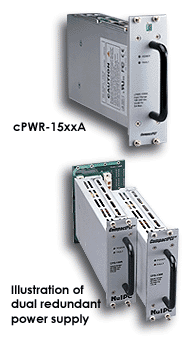
cPS-150R
LOOKING FOR THE RIGHT
INDUSTRIAL SOLUTION?
Discover embedded, communication and automation solutions tailored to your application.
- Redundant Power Architecture: Supports two 3U 31‑pin CompactPCI redundant power supply units (cPS‑150R), enabling hot‑swappable, load‑sharing, and fail‑safe operation.
- PICMG 2.11 Compliance: Fully compliant with the CompactPCI Power Interface Specification (31‑pin variant), ensuring interoperability with standard CompactPCI power modules.
- Dual ATX‑Style DC Output Connectors: Provides two ATX‑compatible 20‑pin DC output connectors for system power distribution.
- External AC Input Terminals: Equipped with screw terminals for direct AC line and neutral input connections.
- Compact 3U Form Factor: Fits standard 3U CompactPCI chassis, occupying a 4‑slot width (approximately 81 mm).
- High Reliability Design: Engineered for industrial environments with robust PCB construction and secure terminal interfaces.
- Signal Integration: Includes standard control and monitoring signals such as INH# (inhibit), FAL# (fail), and DEG# (derate) for system‑level power management.
- Ease of Integration: Designed to mate directly with ADLINK’s cPS‑150R power modules and compatible CompactPCI chassis (e.g., cPCIS‑2000A, cPCIS‑1000).
- Scalable System Support: Can be used in single or dual redundant configurations, supporting both standalone and integrated CompactPCI sub‑systems.
- PICMG 2.11 Compliance: Fully compliant with the CompactPCI Power Interface Specification (31‑pin variant), ensuring interoperability with standard CompactPCI power modules.
- Dual ATX‑Style DC Output Connectors: Provides two ATX‑compatible 20‑pin DC output connectors for system power distribution.
- External AC Input Terminals: Equipped with screw terminals for direct AC line and neutral input connections.
- Compact 3U Form Factor: Fits standard 3U CompactPCI chassis, occupying a 4‑slot width (approximately 81 mm).
- High Reliability Design: Engineered for industrial environments with robust PCB construction and secure terminal interfaces.
- Signal Integration: Includes standard control and monitoring signals such as INH# (inhibit), FAL# (fail), and DEG# (derate) for system‑level power management.
- Ease of Integration: Designed to mate directly with ADLINK’s cPS‑150R power modules and compatible CompactPCI chassis (e.g., cPCIS‑2000A, cPCIS‑1000).
- Scalable System Support: Can be used in single or dual redundant configurations, supporting both standalone and integrated CompactPCI sub‑systems.
1. Product Overview
Product Name: Power Backplane cPCI 3U for cPS‑150R Redundant
Model: cBP‑3052
Series: cBP‑3052/3051 CompactPCI 3U Power Backplane Series
Article Number: cBP‑3052
Manufacturer: ADLINK Technology Inc. (NuIPC® Division)
Product Type: 3U CompactPCI Power Backplane for Dual 31‑pin Redundant Power Supply Units
The ADLINK cBP‑3052 is a dedicated 3U CompactPCI power backplane designed to interface with two cPS‑150R redundant power supply modules. It provides a robust, standards‑compliant power distribution backbone for CompactPCI sub‑systems, ensuring high availability and fault‑tolerant operation in industrial and embedded computing environments. The backplane is part of ADLINK’s cPCIS‑1000/2000 series ecosystem, which includes chassis, power supplies, and peripheral modules for modular CompactPCI platforms.
2. Key Features
- Redundant Power Architecture: Supports two 3U 31‑pin CompactPCI redundant power supply units (cPS‑150R), enabling hot‑swappable, load‑sharing, and fail‑safe operation.
- PICMG 2.11 Compliance: Fully compliant with the CompactPCI Power Interface Specification (31‑pin variant), ensuring interoperability with standard CompactPCI power modules.
- Dual ATX‑Style DC Output Connectors: Provides two ATX‑compatible 20‑pin DC output connectors for system power distribution.
- External AC Input Terminals: Equipped with screw terminals for direct AC line and neutral input connections.
- Compact 3U Form Factor: Fits standard 3U CompactPCI chassis, occupying a 4‑slot width (approximately 81 mm).
- High Reliability Design: Engineered for industrial environments with robust PCB construction and secure terminal interfaces.
- Signal Integration: Includes standard control and monitoring signals such as INH# (inhibit), FAL# (fail), and DEG# (derate) for system‑level power management.
- Ease of Integration: Designed to mate directly with ADLINK’s cPS‑150R power modules and compatible CompactPCI chassis (e.g., cPCIS‑2000A, cPCIS‑1000).
- Scalable System Support: Can be used in single or dual redundant configurations, supporting both standalone and integrated CompactPCI sub‑systems.
3. Technical Specifications
- Form Factor: 3U CompactPCI
- Compliance: PICMG 2.11 (31‑pin CompactPCI Power Interface)
- Supported Power Supplies: Two 3U redundant 31‑pin PSUs (e.g., ADLINK cPS‑150R)
- Dimensions: 133.35 mm (H) × 81.0 mm (W) × 3.2 mm (T)
- Slot Width: 4‑slot equivalent (approx. 20 HP per PSU position)
- Connectors:
- J1, J2: 31‑pin CompactPCI power supply sockets (female)
- CN1, CN2: Dual ATX‑style 20‑pin DC output connectors
- CN5: Screw terminal block for AC input (Line, Neutral, Ground)
- CN7: Screw terminal for chassis ground
- CN13: Screw terminal for +5 V output
- CN15: Screw terminal for +12 V output
- Unpopulated Terminals: CN8–CN12, CN14, CN16 (reserved for optional voltage rails)
- PCB Material: FR‑4 industrial‑grade, 3.2 mm thickness
- Operating Temperature: 0 °C to 70 °C (system dependent)
- Storage Temperature: −40 °C to +85 °C
- Relative Humidity: < 95 % @ 40 °C, non‑condensing
- Weight: Approx. 0.3 kg (bare board)
4. Functionality
The cBP‑3052 serves as the intermediary power distribution backplane between redundant CompactPCI power supply modules and the system’s DC load. Each cPS‑150R PSU plugs into one of the two 31‑pin sockets (J1, J2). The backplane automatically manages current sharing and failover between the two supplies, ensuring uninterrupted power delivery.
Operational Flow:
1. AC Input: External AC mains are connected via CN5 screw terminals.
2. Power Conversion: Each cPS‑150R converts AC to regulated DC outputs (+5 V, +3.3 V, +12 V, −12 V).
3. Redundant Output: The backplane merges outputs from both PSUs, balancing load and providing automatic failover.
4. DC Distribution: Regulated DC power is routed to CN1 and CN2 ATX connectors for system backplanes or peripheral modules.
5. Control Signals: INH#, FAL#, and DEG# lines provide system‑level control, allowing remote power‑on/off, fault detection, and derating indication.
Use Cases:
- Industrial CompactPCI sub‑systems requiring high availability
- Embedded control systems with redundant power requirements
- Telecommunications and data acquisition platforms
- Laboratory instrumentation and automation controllers
Compatibility:
- Fully compatible with ADLINK cPS‑150R redundant PSU
- Integrates with cPCIS‑2000A/2000B and cPCIS‑1000 chassis
- Supports CompactPCI backplanes such as cBP‑3100, cBP‑3200, and cBP‑3400 series
5. Components & Accessories
Included Components:
- cBP‑3052 backplane PCB assembly
- Two 31‑pin CompactPCI PSU sockets (J1, J2)
- Two ATX‑style 20‑pin DC output connectors (CN1, CN2)
- Screw terminal blocks for AC input and DC outputs (CN5, CN7, CN13, CN15)
Optional Accessories:
- cPS‑150R 175 W redundant power supply modules (required for operation)
- Mounting hardware for 3U chassis integration
- ATX power cables for connection to system backplanes
- EMC slot panels (cPCI‑SP3E) for shielding unused slots
Connector Summary:
| Connector | Type | Function | Notes |
|------------|------|-----------|-------|
| J1, J2 | 31‑pin CompactPCI | PSU interface | PICMG 2.11 compliant |
| CN1, CN2 | 20‑pin ATX | DC output | Dual redundant outputs |
| CN5 | Screw terminal | AC input | Line, Neutral, Ground |
| CN7 | Screw terminal | Ground | Chassis earth |
| CN13 | Screw terminal | +5 V output | High‑current rail |
| CN15 | Screw terminal | +12 V output | Auxiliary rail |
6. Installation & Setup
Requirements:
- Compatible 3U CompactPCI chassis (e.g., cPCIS‑2000A)
- Two cPS‑150R redundant power supply modules
- Proper AC mains connection (90–264 VAC, single phase)
- Adequate cooling airflow (≥ 15 CFM recommended)
Mounting Procedure:
1. Power off and disconnect the chassis from mains.
2. Insert the cBP‑3052 into the designated 3U slot (4‑slot width).
3. Secure the backplane using standard card guides and screws.
4. Connect AC input lines to CN5 (Line, Neutral, Ground).
5. Insert two cPS‑150R modules into J1 and J2 connectors.
6. Connect CN1 and CN2 outputs to the system backplane or load.
7. Verify INH# and FAL# signal wiring for remote control and monitoring.
8. Power on the system and confirm LED indicators on PSUs show normal operation.
Configuration Notes:
- The backplane automatically handles load sharing; no manual configuration required.
- Ensure correct polarity on screw terminals to prevent damage.
- For single‑supply operation, one PSU slot may remain unpopulated.
7. Performance & Capabilities
Electrical Performance (with cPS‑150R PSU):
- Total Output Power: 175 W per PSU (350 W combined redundant capacity)
- Output Voltages: +5 V, +3.3 V, +12 V, −12 V
- Current Ratings:
- +5 V @ 20 A (min 2 A)
- +3.3 V @ 12 A
- +12 V @ 2 A
- −12 V @ 1 A
- Voltage Regulation: ±3 % (+5 V), ±5 % (others)
- Ripple: ≤ 1 % p‑p (+5 V, +12 V, −12 V), ≤ 1.5 % p‑p (+3.3 V)
- Efficiency: ~ 73 % typical
- Power Factor: 0.99 typical
- Hold‑Up Time: > 6 ms
- Rise Time: < 200 ms
- Operating Temperature: 0 °C – 70 °C (full power to 40 °C with forced air)
- Protection: Over‑current, over‑voltage, under‑voltage, short‑circuit, thermal shutdown (95 °C)
- MTBF: 50,000 hours (MIL‑HDBK‑217E)
- MTTR: < 5 minutes (module replacement)
Limitations:
- Requires forced‑air cooling for full‑load operation above 40 °C.
- Only compatible with 31‑pin CompactPCI PSUs (not 47‑pin variants).
- Non‑populated terminals (CN8–CN16) are reserved; do not connect external loads.
8. Standards & Compliance
- CompactPCI Compliance: PICMG 2.11 (31‑pin Power Interface)
- Safety Standards: UL 1950, CSA C22.2 No. 950, EN 60950 (TÜV certified)
- EMC/EMI Compliance:
- EN 55022 Class A (radiated and conducted)
- FCC Class A
- EN 61000‑3‑2, EN 61000‑3‑3 (harmonics and flicker)
- EN 50082‑2 (immunity)
- EN 61000‑4‑2/‑3/‑4/‑6/‑8 (ESD, RF, EFT, surge, magnetic field)
- ENV 50204 (RF field immunity)
- Environmental:
- Operating altitude up to 6,400 m
- Relative humidity < 95 % @ 40 °C
- Vibration: 5 Hz–55 Hz, 0.38 mm displacement, 2 cycles/axis
- Shock: per IEC 68‑2‑6 equivalent
9. Additional Information
Warranty:
ADLINK provides a one‑year limited warranty from the date of purchase, covering defects in materials and workmanship. The warranty excludes damage due to misuse, modification, or operation beyond specified limits. Proof of purchase is required for service.
Support & Service:
- Website: [www.adlinktech.com](http://www.adlinktech.com) / [www.adlink.com.tw](http://www.adlink.com.tw)
- Email Contacts:
- General Service: service@adlink.com.tw
- NuIPC Technical Support: nuipc@adlink.com.tw
- Telephone: +886‑2‑82265877
- Fax: +886‑2‑82265717
- Address: 9F, No. 166, Jian Yi Road, Chungho City, Taipei 235, Taiwan, R.O.C.
Maintenance:
- Periodically inspect connectors for dust or oxidation.
- Ensure secure seating of PSU modules.
- Verify fan operation in the chassis to maintain airflow.
- Replace PSUs only with identical cPS‑150R units to maintain redundancy.
Firmware/Hardware Updates:
The cBP‑3052 is a passive backplane with no firmware. Hardware revisions may be released to improve reliability or add connector options; consult ADLINK documentation for revision compatibility.
Service Procedure:
In the event of failure, contact ADLINK technical support with model number, serial number, and system configuration. Units must be returned prepaid and securely packaged.
Summary
The ADLINK cBP‑3052 Power Backplane is a compact, industrial‑grade 3U CompactPCI component engineered for redundant power distribution using dual 31‑pin cPS‑150R power supplies. It provides dual ATX‑style DC outputs, integrated control signaling, and robust mechanical and electrical design compliant with PICMG 2.11 standards. Ideal for mission‑critical CompactPCI systems, it ensures continuous operation, simplified maintenance, and seamless integration within ADLINK’s cPCIS‑1000/2000 series platforms.

Product Name: Power Backplane cPCI 3U for cPS‑150R Redundant
Model: cBP‑3052
Series: cBP‑3052/3051 CompactPCI 3U Power Backplane Series
Article Number: cBP‑3052
Manufacturer: ADLINK Technology Inc. (NuIPC® Division)
Product Type: 3U CompactPCI Power Backplane for Dual 31‑pin Redundant Power Supply Units
The ADLINK cBP‑3052 is a dedicated 3U CompactPCI power backplane designed to interface with two cPS‑150R redundant power supply modules. It provides a robust, standards‑compliant power distribution backbone for CompactPCI sub‑systems, ensuring high availability and fault‑tolerant operation in industrial and embedded computing environments. The backplane is part of ADLINK’s cPCIS‑1000/2000 series ecosystem, which includes chassis, power supplies, and peripheral modules for modular CompactPCI platforms.
2. Key Features
- Redundant Power Architecture: Supports two 3U 31‑pin CompactPCI redundant power supply units (cPS‑150R), enabling hot‑swappable, load‑sharing, and fail‑safe operation.
- PICMG 2.11 Compliance: Fully compliant with the CompactPCI Power Interface Specification (31‑pin variant), ensuring interoperability with standard CompactPCI power modules.
- Dual ATX‑Style DC Output Connectors: Provides two ATX‑compatible 20‑pin DC output connectors for system power distribution.
- External AC Input Terminals: Equipped with screw terminals for direct AC line and neutral input connections.
- Compact 3U Form Factor: Fits standard 3U CompactPCI chassis, occupying a 4‑slot width (approximately 81 mm).
- High Reliability Design: Engineered for industrial environments with robust PCB construction and secure terminal interfaces.
- Signal Integration: Includes standard control and monitoring signals such as INH# (inhibit), FAL# (fail), and DEG# (derate) for system‑level power management.
- Ease of Integration: Designed to mate directly with ADLINK’s cPS‑150R power modules and compatible CompactPCI chassis (e.g., cPCIS‑2000A, cPCIS‑1000).
- Scalable System Support: Can be used in single or dual redundant configurations, supporting both standalone and integrated CompactPCI sub‑systems.
3. Technical Specifications
- Form Factor: 3U CompactPCI
- Compliance: PICMG 2.11 (31‑pin CompactPCI Power Interface)
- Supported Power Supplies: Two 3U redundant 31‑pin PSUs (e.g., ADLINK cPS‑150R)
- Dimensions: 133.35 mm (H) × 81.0 mm (W) × 3.2 mm (T)
- Slot Width: 4‑slot equivalent (approx. 20 HP per PSU position)
- Connectors:
- J1, J2: 31‑pin CompactPCI power supply sockets (female)
- CN1, CN2: Dual ATX‑style 20‑pin DC output connectors
- CN5: Screw terminal block for AC input (Line, Neutral, Ground)
- CN7: Screw terminal for chassis ground
- CN13: Screw terminal for +5 V output
- CN15: Screw terminal for +12 V output
- Unpopulated Terminals: CN8–CN12, CN14, CN16 (reserved for optional voltage rails)
- PCB Material: FR‑4 industrial‑grade, 3.2 mm thickness
- Operating Temperature: 0 °C to 70 °C (system dependent)
- Storage Temperature: −40 °C to +85 °C
- Relative Humidity: < 95 % @ 40 °C, non‑condensing
- Weight: Approx. 0.3 kg (bare board)
4. Functionality
The cBP‑3052 serves as the intermediary power distribution backplane between redundant CompactPCI power supply modules and the system’s DC load. Each cPS‑150R PSU plugs into one of the two 31‑pin sockets (J1, J2). The backplane automatically manages current sharing and failover between the two supplies, ensuring uninterrupted power delivery.
Operational Flow:
1. AC Input: External AC mains are connected via CN5 screw terminals.
2. Power Conversion: Each cPS‑150R converts AC to regulated DC outputs (+5 V, +3.3 V, +12 V, −12 V).
3. Redundant Output: The backplane merges outputs from both PSUs, balancing load and providing automatic failover.
4. DC Distribution: Regulated DC power is routed to CN1 and CN2 ATX connectors for system backplanes or peripheral modules.
5. Control Signals: INH#, FAL#, and DEG# lines provide system‑level control, allowing remote power‑on/off, fault detection, and derating indication.
Use Cases:
- Industrial CompactPCI sub‑systems requiring high availability
- Embedded control systems with redundant power requirements
- Telecommunications and data acquisition platforms
- Laboratory instrumentation and automation controllers
Compatibility:
- Fully compatible with ADLINK cPS‑150R redundant PSU
- Integrates with cPCIS‑2000A/2000B and cPCIS‑1000 chassis
- Supports CompactPCI backplanes such as cBP‑3100, cBP‑3200, and cBP‑3400 series
5. Components & Accessories
Included Components:
- cBP‑3052 backplane PCB assembly
- Two 31‑pin CompactPCI PSU sockets (J1, J2)
- Two ATX‑style 20‑pin DC output connectors (CN1, CN2)
- Screw terminal blocks for AC input and DC outputs (CN5, CN7, CN13, CN15)
Optional Accessories:
- cPS‑150R 175 W redundant power supply modules (required for operation)
- Mounting hardware for 3U chassis integration
- ATX power cables for connection to system backplanes
- EMC slot panels (cPCI‑SP3E) for shielding unused slots
Connector Summary:
| Connector | Type | Function | Notes |
|------------|------|-----------|-------|
| J1, J2 | 31‑pin CompactPCI | PSU interface | PICMG 2.11 compliant |
| CN1, CN2 | 20‑pin ATX | DC output | Dual redundant outputs |
| CN5 | Screw terminal | AC input | Line, Neutral, Ground |
| CN7 | Screw terminal | Ground | Chassis earth |
| CN13 | Screw terminal | +5 V output | High‑current rail |
| CN15 | Screw terminal | +12 V output | Auxiliary rail |
6. Installation & Setup
Requirements:
- Compatible 3U CompactPCI chassis (e.g., cPCIS‑2000A)
- Two cPS‑150R redundant power supply modules
- Proper AC mains connection (90–264 VAC, single phase)
- Adequate cooling airflow (≥ 15 CFM recommended)
Mounting Procedure:
1. Power off and disconnect the chassis from mains.
2. Insert the cBP‑3052 into the designated 3U slot (4‑slot width).
3. Secure the backplane using standard card guides and screws.
4. Connect AC input lines to CN5 (Line, Neutral, Ground).
5. Insert two cPS‑150R modules into J1 and J2 connectors.
6. Connect CN1 and CN2 outputs to the system backplane or load.
7. Verify INH# and FAL# signal wiring for remote control and monitoring.
8. Power on the system and confirm LED indicators on PSUs show normal operation.
Configuration Notes:
- The backplane automatically handles load sharing; no manual configuration required.
- Ensure correct polarity on screw terminals to prevent damage.
- For single‑supply operation, one PSU slot may remain unpopulated.
7. Performance & Capabilities
Electrical Performance (with cPS‑150R PSU):
- Total Output Power: 175 W per PSU (350 W combined redundant capacity)
- Output Voltages: +5 V, +3.3 V, +12 V, −12 V
- Current Ratings:
- +5 V @ 20 A (min 2 A)
- +3.3 V @ 12 A
- +12 V @ 2 A
- −12 V @ 1 A
- Voltage Regulation: ±3 % (+5 V), ±5 % (others)
- Ripple: ≤ 1 % p‑p (+5 V, +12 V, −12 V), ≤ 1.5 % p‑p (+3.3 V)
- Efficiency: ~ 73 % typical
- Power Factor: 0.99 typical
- Hold‑Up Time: > 6 ms
- Rise Time: < 200 ms
- Operating Temperature: 0 °C – 70 °C (full power to 40 °C with forced air)
- Protection: Over‑current, over‑voltage, under‑voltage, short‑circuit, thermal shutdown (95 °C)
- MTBF: 50,000 hours (MIL‑HDBK‑217E)
- MTTR: < 5 minutes (module replacement)
Limitations:
- Requires forced‑air cooling for full‑load operation above 40 °C.
- Only compatible with 31‑pin CompactPCI PSUs (not 47‑pin variants).
- Non‑populated terminals (CN8–CN16) are reserved; do not connect external loads.
8. Standards & Compliance
- CompactPCI Compliance: PICMG 2.11 (31‑pin Power Interface)
- Safety Standards: UL 1950, CSA C22.2 No. 950, EN 60950 (TÜV certified)
- EMC/EMI Compliance:
- EN 55022 Class A (radiated and conducted)
- FCC Class A
- EN 61000‑3‑2, EN 61000‑3‑3 (harmonics and flicker)
- EN 50082‑2 (immunity)
- EN 61000‑4‑2/‑3/‑4/‑6/‑8 (ESD, RF, EFT, surge, magnetic field)
- ENV 50204 (RF field immunity)
- Environmental:
- Operating altitude up to 6,400 m
- Relative humidity < 95 % @ 40 °C
- Vibration: 5 Hz–55 Hz, 0.38 mm displacement, 2 cycles/axis
- Shock: per IEC 68‑2‑6 equivalent
9. Additional Information
Warranty:
ADLINK provides a one‑year limited warranty from the date of purchase, covering defects in materials and workmanship. The warranty excludes damage due to misuse, modification, or operation beyond specified limits. Proof of purchase is required for service.
Support & Service:
- Website: [www.adlinktech.com](http://www.adlinktech.com) / [www.adlink.com.tw](http://www.adlink.com.tw)
- Email Contacts:
- General Service: service@adlink.com.tw
- NuIPC Technical Support: nuipc@adlink.com.tw
- Telephone: +886‑2‑82265877
- Fax: +886‑2‑82265717
- Address: 9F, No. 166, Jian Yi Road, Chungho City, Taipei 235, Taiwan, R.O.C.
Maintenance:
- Periodically inspect connectors for dust or oxidation.
- Ensure secure seating of PSU modules.
- Verify fan operation in the chassis to maintain airflow.
- Replace PSUs only with identical cPS‑150R units to maintain redundancy.
Firmware/Hardware Updates:
The cBP‑3052 is a passive backplane with no firmware. Hardware revisions may be released to improve reliability or add connector options; consult ADLINK documentation for revision compatibility.
Service Procedure:
In the event of failure, contact ADLINK technical support with model number, serial number, and system configuration. Units must be returned prepaid and securely packaged.
Summary
The ADLINK cBP‑3052 Power Backplane is a compact, industrial‑grade 3U CompactPCI component engineered for redundant power distribution using dual 31‑pin cPS‑150R power supplies. It provides dual ATX‑style DC outputs, integrated control signaling, and robust mechanical and electrical design compliant with PICMG 2.11 standards. Ideal for mission‑critical CompactPCI systems, it ensures continuous operation, simplified maintenance, and seamless integration within ADLINK’s cPCIS‑1000/2000 series platforms.
- cPS-150R - cPCI power supply DIN41612, 85..265ACV