LOOKING FOR THE RIGHT
INDUSTRIAL SOLUTION?
Discover embedded, communication and automation solutions tailored to your application.
- Dual‑Channel Pulse‑Train Motion Control:
Two independent pulse‑train output channels for precise motion control of servo or stepper drives.
- High‑Speed Pulse Output:
Supports pulse frequencies up to 4 MHz, enabling high‑resolution and high‑speed motion profiles.
- Encoder Feedback Support:
Two encoder input channels with 20 MHz maximum input frequency (at 4×AB mode), supporting TTL incremental encoders for position and velocity feedback.
- Flexible Output Modes:
Configurable CW/CCW (clockwise/counter‑clockwise) and OUT/DIR (pulse/direction) output modes for compatibility with a wide range of servo and stepper drives.
- Comprehensive Motion and Servo I/O:
Includes dedicated motion I/O (PEL, MEL, ORG) and servo I/O (ALM, INP, RDY, SVON, ERC, RST) interfaces for complete axis control and status monitoring.
- Industrial‑Grade Design:
- Operating temperature: –20 °C to +60 °C
- Isolation: 2 kV DC (channel‑to‑DGND and channel‑to‑chassis)
- Power consumption: < 450 mW (typical)
- Compact form factor: 100 mm (L) × 100 mm (H)
- Hot‑Swappable Module:
Can be replaced or added without powering down the EPS system, reducing mean time to repair (MTTR).
- Standards Compliance:
Fully compliant with IEC 61131 industrial control standards and CiA 402 motion control device profile for EtherCAT.
- Self‑Diagnostics and Health Monitoring:
Integrated temperature and status monitoring with LED indicators for power, status, and emergency stop conditions.
- Quick‑Removable Connectors:
Uses Phoenix Contact DFMC connectors and SCSI VHDCI 68‑pin interfaces for easy wiring and maintenance.
- Compatibility with Major Servo Brands:
Supports dedicated cables for Mitsubishi, Yaskawa, Panasonic, Delta, and general‑purpose servo drives.
Two independent pulse‑train output channels for precise motion control of servo or stepper drives.
- High‑Speed Pulse Output:
Supports pulse frequencies up to 4 MHz, enabling high‑resolution and high‑speed motion profiles.
- Encoder Feedback Support:
Two encoder input channels with 20 MHz maximum input frequency (at 4×AB mode), supporting TTL incremental encoders for position and velocity feedback.
- Flexible Output Modes:
Configurable CW/CCW (clockwise/counter‑clockwise) and OUT/DIR (pulse/direction) output modes for compatibility with a wide range of servo and stepper drives.
- Comprehensive Motion and Servo I/O:
Includes dedicated motion I/O (PEL, MEL, ORG) and servo I/O (ALM, INP, RDY, SVON, ERC, RST) interfaces for complete axis control and status monitoring.
- Industrial‑Grade Design:
- Operating temperature: –20 °C to +60 °C
- Isolation: 2 kV DC (channel‑to‑DGND and channel‑to‑chassis)
- Power consumption: < 450 mW (typical)
- Compact form factor: 100 mm (L) × 100 mm (H)
- Hot‑Swappable Module:
Can be replaced or added without powering down the EPS system, reducing mean time to repair (MTTR).
- Standards Compliance:
Fully compliant with IEC 61131 industrial control standards and CiA 402 motion control device profile for EtherCAT.
- Self‑Diagnostics and Health Monitoring:
Integrated temperature and status monitoring with LED indicators for power, status, and emergency stop conditions.
- Quick‑Removable Connectors:
Uses Phoenix Contact DFMC connectors and SCSI VHDCI 68‑pin interfaces for easy wiring and maintenance.
- Compatibility with Major Servo Brands:
Supports dedicated cables for Mitsubishi, Yaskawa, Panasonic, Delta, and general‑purpose servo drives.
Comprehensive Product Summary – ADLINK EPS‑7002 2‑Channel Pulse‑Train Motion Control EtherCAT Module
*(Approx. 3000 tokens)*
### 1. Product Overview
Product Name: EPS‑7002
Model: EPS‑7002
Series: ADLINK EPS Series EtherCAT Slave System
Article Number: EPS‑7002
Manufacturer: ADLINK Technology, Inc.
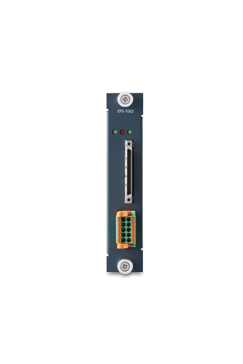
The ADLINK EPS‑7002 is a two‑channel (2‑CH) pulse‑train motion control module designed for EtherCAT‑based distributed automation systems. It is part of ADLINK’s modular EPS Series, a family of EtherCAT slave modules that includes digital I/O, analog I/O, relay, thermal, and motion control modules. The EPS‑7002 provides high‑speed pulse output and encoder feedback capabilities for precise motion control applications, supporting up to 4 MHz pulse output and 20 MHz encoder input frequencies.
The module is engineered for industrial environments, offering a wide operating temperature range of –20 °C to +60 °C, full compliance with IEC 61131 and CiA 402 motion control standards, and hot‑swappable operation for minimal downtime. It integrates seamlessly with ADLINK’s EPS‑6000 EtherCAT bus coupler and EPS‑9905 chassis, forming a complete EtherCAT slave subsystem for machine automation, robotics, and motion control systems.
### 2. Key Features
- Dual‑Channel Pulse‑Train Motion Control:
Two independent pulse‑train output channels for precise motion control of servo or stepper drives.
- High‑Speed Pulse Output:
Supports pulse frequencies up to 4 MHz, enabling high‑resolution and high‑speed motion profiles.
- Encoder Feedback Support:
Two encoder input channels with 20 MHz maximum input frequency (at 4×AB mode), supporting TTL incremental encoders for position and velocity feedback.
- Flexible Output Modes:
Configurable CW/CCW (clockwise/counter‑clockwise) and OUT/DIR (pulse/direction) output modes for compatibility with a wide range of servo and stepper drives.
- Comprehensive Motion and Servo I/O:
Includes dedicated motion I/O (PEL, MEL, ORG) and servo I/O (ALM, INP, RDY, SVON, ERC, RST) interfaces for complete axis control and status monitoring.
- Industrial‑Grade Design:
- Operating temperature: –20 °C to +60 °C
- Isolation: 2 kV DC (channel‑to‑DGND and channel‑to‑chassis)
- Power consumption: < 450 mW (typical)
- Compact form factor: 100 mm (L) × 100 mm (H)
- Hot‑Swappable Module:
Can be replaced or added without powering down the EPS system, reducing mean time to repair (MTTR).
- Standards Compliance:
Fully compliant with IEC 61131 industrial control standards and CiA 402 motion control device profile for EtherCAT.
- Self‑Diagnostics and Health Monitoring:
Integrated temperature and status monitoring with LED indicators for power, status, and emergency stop conditions.
- Quick‑Removable Connectors:
Uses Phoenix Contact DFMC connectors and SCSI VHDCI 68‑pin interfaces for easy wiring and maintenance.
- Compatibility with Major Servo Brands:
Supports dedicated cables for Mitsubishi, Yaskawa, Panasonic, Delta, and general‑purpose servo drives.
### 3. Technical Specifications
| Parameter | Specification |
|----------------|------------------|
| Channels | 2 pulse‑train output channels |
| Pulse Output Frequency | Up to 4 MHz |
| Output Modes | CW/CCW, OUT/DIR |
| Encoder Input Channels | 2 |
| Encoder Input Type | TTL, incremental |
| Encoder Input Frequency | 20 MHz (@ 4×AB mode) |
| Encoder Input Modes | CW/CCW, 1×/2×/4× AB phase |
| Motion I/O Interface | PEL, MEL, ORG |
| Servo I/O Interface | ALM, INP, RDY, SVON, ERC, RST |
| Input Type | Sinking |
| Input Current | IEC 61131‑2 Type 1/3 |
| Output Current (per node) | 50 mA (sinking/sourcing) |
| Power Consumption | < 450 mW (max.) |
| Thermal Dissipation | < 2.55 W (max.) @ EVCC = 24 V + 10 % |
| Operating Temperature | –20 °C to +60 °C |
| Isolation | 2 kV DC (channel‑to‑DGND and channel‑to‑chassis) |
| Dimensions | 100 mm (L) × 100 mm (H) |
| Connector Types | Phoenix Contact DFMC (2×5 pin), SCSI VHDCI 68 pin |
| Hot Swap Support | Yes |
| Compliance | IEC 61131, CiA 402 |
| Mounting | DIN‑rail via EPS‑9905 chassis |
| Weight | Approx. < 200 g (module only) |
### 4. Functionality
The EPS‑7002 functions as a pulse‑train motion control slave module within an EtherCAT network. It generates high‑frequency pulse signals to command servo or stepper drives and simultaneously receives encoder feedback for closed‑loop control.
Operating Principle:
- The EtherCAT master (e.g., ADLINK Talos controller or third‑party master) sends motion commands via the EtherCAT bus.
- The EPS‑7002 interprets these commands according to the CiA 402 motion control profile, generating corresponding pulse‑train outputs.
- Encoder feedback signals are received through TTL incremental inputs, allowing precise position and velocity monitoring.
- Motion and servo I/O signals (limit switches, alarms, ready, and emergency stop) provide real‑time status and safety interlocks.
Use Cases and Applications:
- Multi‑axis servo or stepper motor control in industrial automation.
- Robotics and gantry systems requiring synchronized motion.
- Packaging, labeling, and pick‑and‑place machinery.
- Semiconductor and electronics assembly equipment.
- CNC and precision positioning systems.
Compatibility:
- Works with ADLINK’s EPS‑6000 EtherCAT bus coupler and EPS‑9905 chassis.
- Compatible with ADLINK LinkMasterPro™ configuration software for ESI file generation.
- Supports integration with CoDeSys and other IEC 61131‑3 development environments.
- Operates with both ADLINK and third‑party EtherCAT masters.
### 5. Components & Accessories
Included Components:
- EPS‑7002 module (100 × 100 mm)
- Quick‑removable Phoenix Contact DFMC connector
- User documentation and Quick Start Guide
Connectors:
- Motion I/O Connector: Phoenix Contact DFMC series (1787195), pitch 3.5 mm, 2×5 pin, AWG 16–24 gauge.
- Pin 1 – GND
- Pin 2 – MEL1
- Pin 3 – PEL2
- Pin 4 – MEL2
- Pin 5 – GND
- Pin 6 – PEL1
- Pin 7 – ORG1
- Pin 8 – COM
- Pin 9 – ORG2
- Pin 10 – EMG
- Servo I/O Connector: D‑Sub 26‑pin (via SCSI VHDCI 68‑pin Y‑cable).
Key signals include:
- SVON (Servo On), INP (In‑Position), ERC (Error Clear), RDY (Servo Ready), ALM (Alarm), RST (Reset), EMG (Emergency Stop)
- OUT± (Pulse Output), DIR± (Direction), EA±/EB±/EZ± (Encoder A/B/Z phases)
- COM (+24 V external power), GND (power ground)
Optional Accessories:
- Y‑cable for servo connection (SCSI VHDCI 68‑pin to D‑Sub 26‑pin)
- Dedicated servo cables for Mitsubishi, Yaskawa, Panasonic, Delta, and general‑purpose drives
- DIN‑rail mounting kit (via EPS‑9905 chassis)
- EtherCAT CAT5/CAT5e cables for network connectivity
### 6. Installation & Setup
System Requirements:
- ADLINK EPS‑9905 chassis with available peripheral slot (Slots 1–4)
- EPS‑6000 EtherCAT bus coupler installed and operational
- 24 V DC power supply (± 10 %)
- EtherCAT master controller (ADLINK Talos or third‑party)
Installation Steps:
1. Ensure the EPS‑9905 chassis and EPS‑6000 bus coupler are powered off.
2. Align the EPS‑7002 module with the guide rails of an available slot.
3. Slide the module firmly into place until seated.
4. Tighten the front‑panel thumbscrews to secure the module.
5. Connect motion and servo I/O wiring using the Phoenix Contact and VHDCI connectors.
6. Power up the EPS system.
7. Use LinkMasterPro™ to detect the module and generate the corresponding ESI (EtherCAT Slave Information) file.
8. Import the ESI file into the EtherCAT master configuration software (e.g., CoDeSys).
Configuration:
- LinkMasterPro™ automatically identifies installed EPS modules and generates the ESI XML file.
- The ESI file defines PDO mappings, vendor ID, product code, and communication parameters.
- The module supports COE (CANopen over EtherCAT) and FOE (File over EtherCAT) protocols for configuration and firmware updates.
Mounting:
- DIN‑rail mounting via EPS‑9905 chassis.
- Maintain at least 5 cm clearance above and 2.5 cm on each side for heat dissipation.
### 7. Performance & Capabilities
Motion Control Performance:
- Pulse Output: Up to 4 MHz per channel, supporting high‑speed servo or stepper control.
- Encoder Feedback: 20 MHz input frequency (@ 4×AB mode) for precise position tracking.
- Dual‑Axis Operation: Independent control of two motion channels with synchronized EtherCAT communication.
- Output Modes: CW/CCW and OUT/DIR for flexible drive compatibility.
- I/O Response: Real‑time servo status feedback (ALM, INP, RDY) and motion limit signals (PEL, MEL, ORG).
Electrical & Environmental Performance:
- Power Efficiency: < 450 mW consumption from chassis power.
- Thermal Dissipation: < 2.55 W at maximum load (24 V + 10 %).
- Isolation: 2 kV DC protection between channels and ground.
- Operating Temperature: –20 °C to +60 °C for industrial environments.
- Hot Swap: Yes – module replacement without system shutdown.
Limitations:
- Designed for pulse‑train control; does not support analog velocity or torque control.
- Encoder input limited to TTL incremental type (no absolute encoder support).
- Maximum output current per node is 50 mA (sinking/sourcing).
### 8. Standards & Compliance
- EtherCAT Protocol: Fully compliant with EtherCAT slave specifications.
- Motion Control Profile: Conforms to CiA 402 (Device Profile for Drives and Motion Control).
- Industrial Control Standard: IEC 61131 compliant for I/O and signal characteristics.
- Environmental Compliance:
- RoHS (Restriction of Hazardous Substances)
- WEEE (Waste Electrical and Electronic Equipment)
- EMC and Safety:
- EN 61000‑6 (industrial EMC protection)
- EN 60068‑2 (vibration and shock resistance)
- CE and FCC Class A certified
- UL and CB safety certifications
Environmental Responsibility:
ADLINK ensures that all EPS modules are manufactured in compliance with global environmental standards and encourages proper recycling and disposal at end of life.
### 9. Additional Information
Warranty & Support:
- Standard ADLINK limited hardware warranty (typically 1 year from purchase).
- Technical support available via email and regional offices worldwide.
- Firmware and ESI updates available through ADLINK support portal.
Maintenance:
- Periodically inspect connectors and cabling for wear or damage.
- Ensure adequate ventilation and clean environment to prevent dust accumulation.
- Use LinkMasterPro™ for diagnostics and firmware updates via FOE (File Over EtherCAT).
LED Indicators:
| LED Name | Status | Function |
|---------------|------------|--------------|
| EMG | Lit | Emergency Stop Input active |
| STS | Blinking | Module present / Over‑temperature protection active |
| PWR | Lit | Module power status (normal operation) |
Software Tools:
- LinkMasterPro™ (Windows utility) for module detection, ESI generation, and diagnostics.
- CoDeSys or other IEC 61131‑3 environments for motion programming and integration.
Firmware Update Procedure:
1. Launch LinkMasterPro™ and connect to the EtherCAT network.
2. Use the FOE (File Over EtherCAT) function to upload the new binary file (*.bin).
3. Wait for the “Download Success” notification.
4. Restart the EPS system to activate the new firmware.
Safety Notes:
- Ensure correct 24 V DC input voltage and polarity before powering the system.
- Do not install or remove modules under load unless hot‑swap is confirmed safe.
- Maintain clearance for cooling and avoid exposure to moisture or corrosive environments.
Manufacturer Contact:
ADLINK Technology, Inc.
9F, No. 166 Jian Yi Road, Zhonghe District, New Taipei City 235, Taiwan
Tel: +886‑2‑8226‑5877 Fax: +886‑2‑8226‑5717
Email: service@adlinktech.com Web: [www.adlinktech.com](http://www.adlinktech.com)
### Summary
The ADLINK EPS‑7002 is a compact, high‑performance 2‑channel pulse‑train motion control module engineered for EtherCAT‑based automation systems. It delivers precise, high‑speed motion control with integrated encoder feedback, comprehensive servo I/O, and robust industrial design.
With 4 MHz pulse output, 20 MHz encoder input, and CiA 402 compliance, the EPS‑7002 enables deterministic, synchronized motion control across distributed EtherCAT networks. Its hot‑swappable design, wide temperature tolerance, and 2 kV isolation make it ideal for demanding industrial environments.
When combined with ADLINK’s EPS‑6000 bus coupler and LinkMasterPro™ configuration software, the EPS‑7002 provides a complete, scalable, and reliable motion control solution for modern smart‑factory and machine‑automation applications.
*(Approx. 3000 tokens)*
### 1. Product Overview
Product Name: EPS‑7002
Model: EPS‑7002
Series: ADLINK EPS Series EtherCAT Slave System
Article Number: EPS‑7002
Manufacturer: ADLINK Technology, Inc.
The ADLINK EPS‑7002 is a two‑channel (2‑CH) pulse‑train motion control module designed for EtherCAT‑based distributed automation systems. It is part of ADLINK’s modular EPS Series, a family of EtherCAT slave modules that includes digital I/O, analog I/O, relay, thermal, and motion control modules. The EPS‑7002 provides high‑speed pulse output and encoder feedback capabilities for precise motion control applications, supporting up to 4 MHz pulse output and 20 MHz encoder input frequencies.
The module is engineered for industrial environments, offering a wide operating temperature range of –20 °C to +60 °C, full compliance with IEC 61131 and CiA 402 motion control standards, and hot‑swappable operation for minimal downtime. It integrates seamlessly with ADLINK’s EPS‑6000 EtherCAT bus coupler and EPS‑9905 chassis, forming a complete EtherCAT slave subsystem for machine automation, robotics, and motion control systems.
### 2. Key Features
- Dual‑Channel Pulse‑Train Motion Control:
Two independent pulse‑train output channels for precise motion control of servo or stepper drives.
- High‑Speed Pulse Output:
Supports pulse frequencies up to 4 MHz, enabling high‑resolution and high‑speed motion profiles.
- Encoder Feedback Support:
Two encoder input channels with 20 MHz maximum input frequency (at 4×AB mode), supporting TTL incremental encoders for position and velocity feedback.
- Flexible Output Modes:
Configurable CW/CCW (clockwise/counter‑clockwise) and OUT/DIR (pulse/direction) output modes for compatibility with a wide range of servo and stepper drives.
- Comprehensive Motion and Servo I/O:
Includes dedicated motion I/O (PEL, MEL, ORG) and servo I/O (ALM, INP, RDY, SVON, ERC, RST) interfaces for complete axis control and status monitoring.
- Industrial‑Grade Design:
- Operating temperature: –20 °C to +60 °C
- Isolation: 2 kV DC (channel‑to‑DGND and channel‑to‑chassis)
- Power consumption: < 450 mW (typical)
- Compact form factor: 100 mm (L) × 100 mm (H)
- Hot‑Swappable Module:
Can be replaced or added without powering down the EPS system, reducing mean time to repair (MTTR).
- Standards Compliance:
Fully compliant with IEC 61131 industrial control standards and CiA 402 motion control device profile for EtherCAT.
- Self‑Diagnostics and Health Monitoring:
Integrated temperature and status monitoring with LED indicators for power, status, and emergency stop conditions.
- Quick‑Removable Connectors:
Uses Phoenix Contact DFMC connectors and SCSI VHDCI 68‑pin interfaces for easy wiring and maintenance.
- Compatibility with Major Servo Brands:
Supports dedicated cables for Mitsubishi, Yaskawa, Panasonic, Delta, and general‑purpose servo drives.
### 3. Technical Specifications
| Parameter | Specification |
|----------------|------------------|
| Channels | 2 pulse‑train output channels |
| Pulse Output Frequency | Up to 4 MHz |
| Output Modes | CW/CCW, OUT/DIR |
| Encoder Input Channels | 2 |
| Encoder Input Type | TTL, incremental |
| Encoder Input Frequency | 20 MHz (@ 4×AB mode) |
| Encoder Input Modes | CW/CCW, 1×/2×/4× AB phase |
| Motion I/O Interface | PEL, MEL, ORG |
| Servo I/O Interface | ALM, INP, RDY, SVON, ERC, RST |
| Input Type | Sinking |
| Input Current | IEC 61131‑2 Type 1/3 |
| Output Current (per node) | 50 mA (sinking/sourcing) |
| Power Consumption | < 450 mW (max.) |
| Thermal Dissipation | < 2.55 W (max.) @ EVCC = 24 V + 10 % |
| Operating Temperature | –20 °C to +60 °C |
| Isolation | 2 kV DC (channel‑to‑DGND and channel‑to‑chassis) |
| Dimensions | 100 mm (L) × 100 mm (H) |
| Connector Types | Phoenix Contact DFMC (2×5 pin), SCSI VHDCI 68 pin |
| Hot Swap Support | Yes |
| Compliance | IEC 61131, CiA 402 |
| Mounting | DIN‑rail via EPS‑9905 chassis |
| Weight | Approx. < 200 g (module only) |
### 4. Functionality
The EPS‑7002 functions as a pulse‑train motion control slave module within an EtherCAT network. It generates high‑frequency pulse signals to command servo or stepper drives and simultaneously receives encoder feedback for closed‑loop control.
Operating Principle:
- The EtherCAT master (e.g., ADLINK Talos controller or third‑party master) sends motion commands via the EtherCAT bus.
- The EPS‑7002 interprets these commands according to the CiA 402 motion control profile, generating corresponding pulse‑train outputs.
- Encoder feedback signals are received through TTL incremental inputs, allowing precise position and velocity monitoring.
- Motion and servo I/O signals (limit switches, alarms, ready, and emergency stop) provide real‑time status and safety interlocks.
Use Cases and Applications:
- Multi‑axis servo or stepper motor control in industrial automation.
- Robotics and gantry systems requiring synchronized motion.
- Packaging, labeling, and pick‑and‑place machinery.
- Semiconductor and electronics assembly equipment.
- CNC and precision positioning systems.
Compatibility:
- Works with ADLINK’s EPS‑6000 EtherCAT bus coupler and EPS‑9905 chassis.
- Compatible with ADLINK LinkMasterPro™ configuration software for ESI file generation.
- Supports integration with CoDeSys and other IEC 61131‑3 development environments.
- Operates with both ADLINK and third‑party EtherCAT masters.
### 5. Components & Accessories
Included Components:
- EPS‑7002 module (100 × 100 mm)
- Quick‑removable Phoenix Contact DFMC connector
- User documentation and Quick Start Guide
Connectors:
- Motion I/O Connector: Phoenix Contact DFMC series (1787195), pitch 3.5 mm, 2×5 pin, AWG 16–24 gauge.
- Pin 1 – GND
- Pin 2 – MEL1
- Pin 3 – PEL2
- Pin 4 – MEL2
- Pin 5 – GND
- Pin 6 – PEL1
- Pin 7 – ORG1
- Pin 8 – COM
- Pin 9 – ORG2
- Pin 10 – EMG
- Servo I/O Connector: D‑Sub 26‑pin (via SCSI VHDCI 68‑pin Y‑cable).
Key signals include:
- SVON (Servo On), INP (In‑Position), ERC (Error Clear), RDY (Servo Ready), ALM (Alarm), RST (Reset), EMG (Emergency Stop)
- OUT± (Pulse Output), DIR± (Direction), EA±/EB±/EZ± (Encoder A/B/Z phases)
- COM (+24 V external power), GND (power ground)
Optional Accessories:
- Y‑cable for servo connection (SCSI VHDCI 68‑pin to D‑Sub 26‑pin)
- Dedicated servo cables for Mitsubishi, Yaskawa, Panasonic, Delta, and general‑purpose drives
- DIN‑rail mounting kit (via EPS‑9905 chassis)
- EtherCAT CAT5/CAT5e cables for network connectivity
### 6. Installation & Setup
System Requirements:
- ADLINK EPS‑9905 chassis with available peripheral slot (Slots 1–4)
- EPS‑6000 EtherCAT bus coupler installed and operational
- 24 V DC power supply (± 10 %)
- EtherCAT master controller (ADLINK Talos or third‑party)
Installation Steps:
1. Ensure the EPS‑9905 chassis and EPS‑6000 bus coupler are powered off.
2. Align the EPS‑7002 module with the guide rails of an available slot.
3. Slide the module firmly into place until seated.
4. Tighten the front‑panel thumbscrews to secure the module.
5. Connect motion and servo I/O wiring using the Phoenix Contact and VHDCI connectors.
6. Power up the EPS system.
7. Use LinkMasterPro™ to detect the module and generate the corresponding ESI (EtherCAT Slave Information) file.
8. Import the ESI file into the EtherCAT master configuration software (e.g., CoDeSys).
Configuration:
- LinkMasterPro™ automatically identifies installed EPS modules and generates the ESI XML file.
- The ESI file defines PDO mappings, vendor ID, product code, and communication parameters.
- The module supports COE (CANopen over EtherCAT) and FOE (File over EtherCAT) protocols for configuration and firmware updates.
Mounting:
- DIN‑rail mounting via EPS‑9905 chassis.
- Maintain at least 5 cm clearance above and 2.5 cm on each side for heat dissipation.
### 7. Performance & Capabilities
Motion Control Performance:
- Pulse Output: Up to 4 MHz per channel, supporting high‑speed servo or stepper control.
- Encoder Feedback: 20 MHz input frequency (@ 4×AB mode) for precise position tracking.
- Dual‑Axis Operation: Independent control of two motion channels with synchronized EtherCAT communication.
- Output Modes: CW/CCW and OUT/DIR for flexible drive compatibility.
- I/O Response: Real‑time servo status feedback (ALM, INP, RDY) and motion limit signals (PEL, MEL, ORG).
Electrical & Environmental Performance:
- Power Efficiency: < 450 mW consumption from chassis power.
- Thermal Dissipation: < 2.55 W at maximum load (24 V + 10 %).
- Isolation: 2 kV DC protection between channels and ground.
- Operating Temperature: –20 °C to +60 °C for industrial environments.
- Hot Swap: Yes – module replacement without system shutdown.
Limitations:
- Designed for pulse‑train control; does not support analog velocity or torque control.
- Encoder input limited to TTL incremental type (no absolute encoder support).
- Maximum output current per node is 50 mA (sinking/sourcing).
### 8. Standards & Compliance
- EtherCAT Protocol: Fully compliant with EtherCAT slave specifications.
- Motion Control Profile: Conforms to CiA 402 (Device Profile for Drives and Motion Control).
- Industrial Control Standard: IEC 61131 compliant for I/O and signal characteristics.
- Environmental Compliance:
- RoHS (Restriction of Hazardous Substances)
- WEEE (Waste Electrical and Electronic Equipment)
- EMC and Safety:
- EN 61000‑6 (industrial EMC protection)
- EN 60068‑2 (vibration and shock resistance)
- CE and FCC Class A certified
- UL and CB safety certifications
Environmental Responsibility:
ADLINK ensures that all EPS modules are manufactured in compliance with global environmental standards and encourages proper recycling and disposal at end of life.
### 9. Additional Information
Warranty & Support:
- Standard ADLINK limited hardware warranty (typically 1 year from purchase).
- Technical support available via email and regional offices worldwide.
- Firmware and ESI updates available through ADLINK support portal.
Maintenance:
- Periodically inspect connectors and cabling for wear or damage.
- Ensure adequate ventilation and clean environment to prevent dust accumulation.
- Use LinkMasterPro™ for diagnostics and firmware updates via FOE (File Over EtherCAT).
LED Indicators:
| LED Name | Status | Function |
|---------------|------------|--------------|
| EMG | Lit | Emergency Stop Input active |
| STS | Blinking | Module present / Over‑temperature protection active |
| PWR | Lit | Module power status (normal operation) |
Software Tools:
- LinkMasterPro™ (Windows utility) for module detection, ESI generation, and diagnostics.
- CoDeSys or other IEC 61131‑3 environments for motion programming and integration.
Firmware Update Procedure:
1. Launch LinkMasterPro™ and connect to the EtherCAT network.
2. Use the FOE (File Over EtherCAT) function to upload the new binary file (*.bin).
3. Wait for the “Download Success” notification.
4. Restart the EPS system to activate the new firmware.
Safety Notes:
- Ensure correct 24 V DC input voltage and polarity before powering the system.
- Do not install or remove modules under load unless hot‑swap is confirmed safe.
- Maintain clearance for cooling and avoid exposure to moisture or corrosive environments.
Manufacturer Contact:
ADLINK Technology, Inc.
9F, No. 166 Jian Yi Road, Zhonghe District, New Taipei City 235, Taiwan
Tel: +886‑2‑8226‑5877 Fax: +886‑2‑8226‑5717
Email: service@adlinktech.com Web: [www.adlinktech.com](http://www.adlinktech.com)
### Summary
The ADLINK EPS‑7002 is a compact, high‑performance 2‑channel pulse‑train motion control module engineered for EtherCAT‑based automation systems. It delivers precise, high‑speed motion control with integrated encoder feedback, comprehensive servo I/O, and robust industrial design.
With 4 MHz pulse output, 20 MHz encoder input, and CiA 402 compliance, the EPS‑7002 enables deterministic, synchronized motion control across distributed EtherCAT networks. Its hot‑swappable design, wide temperature tolerance, and 2 kV isolation make it ideal for demanding industrial environments.
When combined with ADLINK’s EPS‑6000 bus coupler and LinkMasterPro™ configuration software, the EPS‑7002 provides a complete, scalable, and reliable motion control solution for modern smart‑factory and machine‑automation applications.
-
 EPS-7002_Datasheet_en_1.pdf
PDF Catalog
EPS-7002_Datasheet_en_1.pdf
PDF Catalog
-
 EPS-7002_QuickStart_en_1.pdf
Manual
EPS-7002_QuickStart_en_1.pdf
Manual

No accessories available.