LOOKING FOR THE RIGHT
INDUSTRIAL SOLUTION?
Discover embedded, communication and automation solutions tailored to your application.
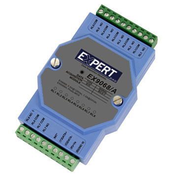
EX9068D-M
8*Relay output, RS485, LED, Modbus
171,00 EUR
including VAT 203.49 EUR
- 8 Independent Relay Outputs:
Eight Form‑A (normally open) relay channels for digital output control of external devices such as solenoids, lamps, contactors, or alarms.
- RS‑485 Communication Interface:
Two‑wire RS‑485 interface supporting multi‑drop networking of up to 256 modules on a single bus, with a maximum cable length of 1200 m (without repeater).
- Modbus RTU and ASCII Protocols:
Fully compatible with Modbus RTU for industrial interoperability; also supports ASCII command mode for direct serial control and configuration.
- LED Channel Indicators:
Each output channel includes a dedicated LED for real‑time status indication, simplifying diagnostics and monitoring.
- Wide Power Supply Range:
Operates from +10 VDC to +30 VDC, allowing flexible integration with various industrial power systems.
- Galvanic Isolation:
Input/output isolation ensures electrical protection between communication lines and relay circuits, improving system safety and noise immunity.
- Dual Watchdog System:
Hardware and software watchdogs monitor both module and host operation, automatically resetting or switching outputs to safe states in case of communication failure.
- Extended Temperature Range:
Designed for operation in demanding environments, with an operating range from ‑25 °C to +75 °C and storage range from ‑30 °C to +75 °C.
- Compact, Rugged Design:
Industrial‑grade enclosure suitable for DIN‑rail or panel mounting, optimized for distributed I/O applications.
- Manual or Software Configuration:
Module parameters (address, baud rate, protocol mode) can be configured via ASCII commands, Modbus registers, or the ExpertDAQ configuration utility.
Eight Form‑A (normally open) relay channels for digital output control of external devices such as solenoids, lamps, contactors, or alarms.
- RS‑485 Communication Interface:
Two‑wire RS‑485 interface supporting multi‑drop networking of up to 256 modules on a single bus, with a maximum cable length of 1200 m (without repeater).
- Modbus RTU and ASCII Protocols:
Fully compatible with Modbus RTU for industrial interoperability; also supports ASCII command mode for direct serial control and configuration.
- LED Channel Indicators:
Each output channel includes a dedicated LED for real‑time status indication, simplifying diagnostics and monitoring.
- Wide Power Supply Range:
Operates from +10 VDC to +30 VDC, allowing flexible integration with various industrial power systems.
- Galvanic Isolation:
Input/output isolation ensures electrical protection between communication lines and relay circuits, improving system safety and noise immunity.
- Dual Watchdog System:
Hardware and software watchdogs monitor both module and host operation, automatically resetting or switching outputs to safe states in case of communication failure.
- Extended Temperature Range:
Designed for operation in demanding environments, with an operating range from ‑25 °C to +75 °C and storage range from ‑30 °C to +75 °C.
- Compact, Rugged Design:
Industrial‑grade enclosure suitable for DIN‑rail or panel mounting, optimized for distributed I/O applications.
- Manual or Software Configuration:
Module parameters (address, baud rate, protocol mode) can be configured via ASCII commands, Modbus registers, or the ExpertDAQ configuration utility.
Comprehensive Product Summary – ExpertDAQ EX9068D‑M Relay Output Module
### 1. Product Overview
Product Name: ExpertDAQ EX9068D‑M
Model Number: EX9068D‑M
Series: EX9000 Series Distributed I/O Modules
Article Number: EX9068D‑M
Manufacturer: ExpertDAQ (Expert Data Acquisition Systems)
The ExpertDAQ EX9068D‑M is an industrial‑grade 8‑channel relay output module designed for distributed control and monitoring applications over RS‑485 networks. It supports Modbus RTU communication and ASCII command protocols, enabling seamless integration into SCADA, PLC, and industrial automation systems. The module provides eight Form‑A (normally open) relay outputs, each capable of switching up to 1 A at 24 VDC or 0.5 A at 120 VAC. It features per‑channel LED indicators, galvanic isolation, and dual watchdog protection for enhanced reliability in harsh environments.
### 2. Key Features
- 8 Independent Relay Outputs:
Eight Form‑A (normally open) relay channels for digital output control of external devices such as solenoids, lamps, contactors, or alarms.
- RS‑485 Communication Interface:
Two‑wire RS‑485 interface supporting multi‑drop networking of up to 256 modules on a single bus, with a maximum cable length of 1200 m (without repeater).
- Modbus RTU and ASCII Protocols:
Fully compatible with Modbus RTU for industrial interoperability; also supports ASCII command mode for direct serial control and configuration.
- LED Channel Indicators:
Each output channel includes a dedicated LED for real‑time status indication, simplifying diagnostics and monitoring.
- Wide Power Supply Range:
Operates from +10 VDC to +30 VDC, allowing flexible integration with various industrial power systems.
- Galvanic Isolation:
Input/output isolation ensures electrical protection between communication lines and relay circuits, improving system safety and noise immunity.
- Dual Watchdog System:
Hardware and software watchdogs monitor both module and host operation, automatically resetting or switching outputs to safe states in case of communication failure.
- Extended Temperature Range:
Designed for operation in demanding environments, with an operating range from ‑25 °C to +75 °C and storage range from ‑30 °C to +75 °C.
- Compact, Rugged Design:
Industrial‑grade enclosure suitable for DIN‑rail or panel mounting, optimized for distributed I/O applications.
- Manual or Software Configuration:
Module parameters (address, baud rate, protocol mode) can be configured via ASCII commands, Modbus registers, or the ExpertDAQ configuration utility.
### 3. Technical Specifications
| Parameter | Specification |
|----------------|-------------------|
| Interface | RS‑485, 2‑wire |
| Communication Speed | 1200, 2400, 4800, 9600, 19.2 k, 38.4 k, 57.6 k, 115.2 k bps |
| Protocol Support | Modbus RTU, ASCII command mode |
| Output Channels | 8 × Relay outputs (Form A, normally open) |
| Relay Contact Rating | 1.0 A @ 24 VDC (max), 0.5 A @ 120 VAC (max) |
| Operate Time | ≤ 5 ms |
| Release Time | ≤ 2 ms |
| Surge Strength | 1500 V |
| Minimum Mechanical Life | ≥ 10⁵ operations |
| Isolation Voltage | I/O galvanic isolation (typical 1500 V) |
| Power Supply | +10 VDC to +30 VDC |
| Power Consumption | 1.4 W typical |
| Digital Level 0 | < +1 V |
| Digital Level 1 | 4 – 30 V |
| LED Indicators | 8 × output status LEDs |
| Operating Temperature | ‑25 °C to +75 °C |
| Storage Temperature | ‑30 °C to +75 °C |
| Communication Distance | Up to 1200 m (4000 ft) without repeater |
| Network Capacity | Up to 256 modules per RS‑485 network |
| Mounting | DIN‑rail or panel mount |
| Enclosure | Industrial plastic housing |
| Weight | Approx. 150 – 200 g (typical for EX9000 modules) |
### 4. Functionality
The EX9068D‑M functions as a distributed digital output module that communicates with a host controller (PLC, PC, or HMI) via RS‑485. Each of its eight relay outputs can be individually controlled through Modbus RTU commands or ASCII instructions. The module’s internal microcontroller interprets incoming serial commands and actuates the corresponding relay contacts.
Typical Use Cases:
- Industrial automation and process control
- Remote equipment switching and monitoring
- Building automation (lighting, HVAC, access control)
- Energy management and power distribution systems
- Laboratory instrumentation and test benches
- Telecommunication and data acquisition systems
Compatibility:
- Compatible with Modbus RTU master devices such as PLCs, SCADA systems, and industrial PCs.
- Integrates with ExpertDAQ’s EX9000 series I/O modules for scalable distributed control networks.
- Supports both ASCII and Modbus command sets for flexible integration.
### 5. Components & Accessories
Included Components:
- EX9068D‑M module unit
- Quick start guide and configuration instructions
- Terminal block connectors for power and RS‑485 wiring
- Built‑in INIT* switch for configuration reset
Optional Accessories:
- RS‑485 repeaters or converters (for extended distance or USB/RS‑232 interfacing)
- DIN‑rail mounting clips and brackets
- ExpertDAQ configuration software utility
- External power supply (10–30 VDC regulated)
Connectors:
- RS‑485 Port: 2‑wire differential (Data +, Data –)
- Power Input: +10 VDC to +30 VDC terminal
- Relay Outputs: 8 × Form A contacts with individual commons
- INIT* Terminal/Switch: Used for entering configuration mode
### 6. Installation & Setup
Requirements:
- DC power source (10–30 VDC, ≥ 1.4 W)
- RS‑485 network connection (twisted‑pair shielded cable recommended)
- Host controller supporting Modbus RTU or ASCII protocol
Mounting Options:
- DIN‑rail mounting for control cabinets
- Panel mounting using screws or brackets
Configuration Procedure:
1. Default Settings:
- Module Address: 01
- Baud Rate: 9600 bps
- Protocol: Modbus RTU
- DIO Type: 40
2. INIT* Mode:
- Activate by sliding the INIT* switch to the “Init” position (rear side) or shorting INIT* to GND.
- Power on the module to enter configuration mode.
- Use ASCII commands to modify address, baud rate, or protocol.
- Return switch to “Normal” position and power cycle to apply new settings.
3. Network Wiring:
- Connect RS‑485 Data + and Data – lines in parallel across all modules.
- Terminate both ends of the RS‑485 bus with 120 Ω resistors if required.
- Ensure proper grounding and shielding to minimize noise.
4. Power Connection:
- Connect +VDC (10–30 V) and GND to the power terminals.
- Verify polarity before powering on.
5. Verification:
- Observe LED indicators for power and channel status.
- Use Modbus or ASCII commands to test relay switching.
### 7. Performance & Capabilities
Switching Performance:
- Relay operate time ≤ 5 ms; release time ≤ 2 ms ensures responsive control.
- Contact life ≥ 100,000 operations under rated load.
- Surge strength up to 1500 V provides transient protection.
Communication Performance:
- Baud rates up to 115.2 kbps for high‑speed data exchange.
- Supports up to 256 modules per RS‑485 network.
- Communication distance up to 1200 m without repeater.
Power Efficiency:
- Low power consumption (1.4 W typical) minimizes heat generation and allows dense module installations.
Reliability Features:
- Dual Watchdog System:
- *Module Watchdog* monitors internal operation and resets the module if a fault occurs.
- *Host Watchdog* monitors communication from the master; if timeout occurs, outputs revert to predefined safe values.
- Safe and Power‑On Values:
- Each output can be assigned a “Power‑On Value” (state after reset) and a “Safe Value” (state after communication loss).
- These values are stored in EEPROM and can be configured via Modbus or ASCII commands.
Limitations:
- Relay outputs are mechanical; not suitable for high‑frequency switching.
- Maximum load limited to 1 A @ 24 VDC or 0.5 A @ 120 VAC.
- For higher current or faster switching, ExpertDAQ offers PhotoMOS variants (e.g., EX9068AD‑M).
### 8. Standards & Compliance
Communication Standards:
- RS‑485 (EIA/TIA‑485) compliant differential signaling
- Modbus RTU protocol compliant with Modbus Organization specifications
- ASCII command protocol for direct serial control
Electrical & Safety:
- Galvanic isolation between I/O and communication lines
- Surge protection up to 1500 V
- Designed for industrial EMC environments
Environmental Compliance:
- Operating temperature: ‑25 °C to +75 °C
- Storage temperature: ‑30 °C to +75 °C
- Suitable for industrial and field installations
Quality & Reliability:
- Manufactured under ISO‑compliant quality control
- Long‑life relays rated for ≥ 10⁵ operations
- Conforms to CE and RoHS directives (typical for ExpertDAQ modules)
### 9. Additional Information
Warranty & Support:
- Standard manufacturer warranty (typically 2 years; confirm with supplier)
- Technical support and firmware updates available from ExpertDAQ
- Comprehensive documentation including command sets, Modbus mapping, and wiring diagrams
Maintenance:
- Periodic inspection of relay contacts recommended for high‑load applications
- Ensure clean, dry environment to prevent corrosion or dust accumulation
- Firmware and configuration can be updated via RS‑485 interface
Firmware & Configuration Management:
- Firmware version readable via command `$AAF` (returns version string, e.g., D03.11)
- Module name and address configurable via ASCII commands (`~AAO`, `%AANNTTCCFF`)
- EEPROM stores configuration parameters (address, baud rate, protocol, safe/power‑on values)
Modbus Mapping Overview:
- Coils (00001–00008): Digital output channels (ON/OFF)
- Registers (00129–00136): Safe values for each output
- Registers (00161–00168): Power‑on values for each output
- Register (40489): Watchdog timeout value (0–255 × 0.1 s)
- Register (00261): Watchdog enable/disable
- Register (00270): Watchdog timeout status
- Register (40483–40484): Module name
- Register (40485): Module address
- Register (40486): Baud rate setting
- Register (00257): Protocol mode (ASCII = 0, Modbus RTU = 1)
Command Examples (ASCII Mode):
- `@01FF` → Set all outputs ON
- `$016` → Read digital output status
- `~015P` → Set current output as Power‑On value
- `~015S` → Set current output as Safe value
- `$01F` → Read firmware version
- `$01P1` → Set protocol to Modbus RTU mode
Safety & Reliability Notes:
- Host watchdog timeout automatically sets outputs to Safe Value to prevent unintended operation.
- Module watchdog ensures self‑recovery from transient faults.
- INIT* mode provides recovery mechanism for forgotten configuration parameters.
Firmware Update & Configuration Utility:
- ExpertDAQ provides a PC‑based configuration tool for setting addresses, baud rates, and protocol modes.
- Updates and utilities available from the manufacturer’s website.
### Summary
The ExpertDAQ EX9068D‑M is a robust, versatile 8‑channel relay output module engineered for industrial automation and remote control applications. Its combination of Modbus RTU compatibility, RS‑485 networking, and dual watchdog protection ensures reliable operation in distributed control systems. With flexible configuration options, LED status indicators, and wide environmental tolerance, the EX9068D‑M delivers dependable performance for controlling digital outputs in manufacturing, building automation, and process control environments.
Key Highlights Recap:
- 8 × Form A relay outputs (1 A @ 24 VDC / 0.5 A @ 120 VAC)
- RS‑485 2‑wire interface, Modbus RTU / ASCII protocols
- Power supply: 10–30 VDC, 1.4 W consumption
- Dual watchdog (hardware + software)
- LED indicators per channel
- Operating temperature: ‑25 °C to +75 °C
- Galvanic isolation and surge protection
- Configurable safe and power‑on output states
- Up to 256 modules per RS‑485 network
- Ideal for industrial, building, and process automation systems
Manufacturer Contact:
ExpertDAQ – Expert Data Acquisition Systems
Website: [www.expertdaQ.com](https://www.expertdaQ.com)
Support: support@expertdaQ.com
*(All specifications subject to change without notice. Verify with the latest manufacturer documentation before deployment.)*
### 1. Product Overview
Product Name: ExpertDAQ EX9068D‑M
Model Number: EX9068D‑M
Series: EX9000 Series Distributed I/O Modules
Article Number: EX9068D‑M
Manufacturer: ExpertDAQ (Expert Data Acquisition Systems)
The ExpertDAQ EX9068D‑M is an industrial‑grade 8‑channel relay output module designed for distributed control and monitoring applications over RS‑485 networks. It supports Modbus RTU communication and ASCII command protocols, enabling seamless integration into SCADA, PLC, and industrial automation systems. The module provides eight Form‑A (normally open) relay outputs, each capable of switching up to 1 A at 24 VDC or 0.5 A at 120 VAC. It features per‑channel LED indicators, galvanic isolation, and dual watchdog protection for enhanced reliability in harsh environments.
### 2. Key Features
- 8 Independent Relay Outputs:
Eight Form‑A (normally open) relay channels for digital output control of external devices such as solenoids, lamps, contactors, or alarms.
- RS‑485 Communication Interface:
Two‑wire RS‑485 interface supporting multi‑drop networking of up to 256 modules on a single bus, with a maximum cable length of 1200 m (without repeater).
- Modbus RTU and ASCII Protocols:
Fully compatible with Modbus RTU for industrial interoperability; also supports ASCII command mode for direct serial control and configuration.
- LED Channel Indicators:
Each output channel includes a dedicated LED for real‑time status indication, simplifying diagnostics and monitoring.
- Wide Power Supply Range:
Operates from +10 VDC to +30 VDC, allowing flexible integration with various industrial power systems.
- Galvanic Isolation:
Input/output isolation ensures electrical protection between communication lines and relay circuits, improving system safety and noise immunity.
- Dual Watchdog System:
Hardware and software watchdogs monitor both module and host operation, automatically resetting or switching outputs to safe states in case of communication failure.
- Extended Temperature Range:
Designed for operation in demanding environments, with an operating range from ‑25 °C to +75 °C and storage range from ‑30 °C to +75 °C.
- Compact, Rugged Design:
Industrial‑grade enclosure suitable for DIN‑rail or panel mounting, optimized for distributed I/O applications.
- Manual or Software Configuration:
Module parameters (address, baud rate, protocol mode) can be configured via ASCII commands, Modbus registers, or the ExpertDAQ configuration utility.
### 3. Technical Specifications
| Parameter | Specification |
|----------------|-------------------|
| Interface | RS‑485, 2‑wire |
| Communication Speed | 1200, 2400, 4800, 9600, 19.2 k, 38.4 k, 57.6 k, 115.2 k bps |
| Protocol Support | Modbus RTU, ASCII command mode |
| Output Channels | 8 × Relay outputs (Form A, normally open) |
| Relay Contact Rating | 1.0 A @ 24 VDC (max), 0.5 A @ 120 VAC (max) |
| Operate Time | ≤ 5 ms |
| Release Time | ≤ 2 ms |
| Surge Strength | 1500 V |
| Minimum Mechanical Life | ≥ 10⁵ operations |
| Isolation Voltage | I/O galvanic isolation (typical 1500 V) |
| Power Supply | +10 VDC to +30 VDC |
| Power Consumption | 1.4 W typical |
| Digital Level 0 | < +1 V |
| Digital Level 1 | 4 – 30 V |
| LED Indicators | 8 × output status LEDs |
| Operating Temperature | ‑25 °C to +75 °C |
| Storage Temperature | ‑30 °C to +75 °C |
| Communication Distance | Up to 1200 m (4000 ft) without repeater |
| Network Capacity | Up to 256 modules per RS‑485 network |
| Mounting | DIN‑rail or panel mount |
| Enclosure | Industrial plastic housing |
| Weight | Approx. 150 – 200 g (typical for EX9000 modules) |
### 4. Functionality
The EX9068D‑M functions as a distributed digital output module that communicates with a host controller (PLC, PC, or HMI) via RS‑485. Each of its eight relay outputs can be individually controlled through Modbus RTU commands or ASCII instructions. The module’s internal microcontroller interprets incoming serial commands and actuates the corresponding relay contacts.
Typical Use Cases:
- Industrial automation and process control
- Remote equipment switching and monitoring
- Building automation (lighting, HVAC, access control)
- Energy management and power distribution systems
- Laboratory instrumentation and test benches
- Telecommunication and data acquisition systems
Compatibility:
- Compatible with Modbus RTU master devices such as PLCs, SCADA systems, and industrial PCs.
- Integrates with ExpertDAQ’s EX9000 series I/O modules for scalable distributed control networks.
- Supports both ASCII and Modbus command sets for flexible integration.
### 5. Components & Accessories
Included Components:
- EX9068D‑M module unit
- Quick start guide and configuration instructions
- Terminal block connectors for power and RS‑485 wiring
- Built‑in INIT* switch for configuration reset
Optional Accessories:
- RS‑485 repeaters or converters (for extended distance or USB/RS‑232 interfacing)
- DIN‑rail mounting clips and brackets
- ExpertDAQ configuration software utility
- External power supply (10–30 VDC regulated)
Connectors:
- RS‑485 Port: 2‑wire differential (Data +, Data –)
- Power Input: +10 VDC to +30 VDC terminal
- Relay Outputs: 8 × Form A contacts with individual commons
- INIT* Terminal/Switch: Used for entering configuration mode
### 6. Installation & Setup
Requirements:
- DC power source (10–30 VDC, ≥ 1.4 W)
- RS‑485 network connection (twisted‑pair shielded cable recommended)
- Host controller supporting Modbus RTU or ASCII protocol
Mounting Options:
- DIN‑rail mounting for control cabinets
- Panel mounting using screws or brackets
Configuration Procedure:
1. Default Settings:
- Module Address: 01
- Baud Rate: 9600 bps
- Protocol: Modbus RTU
- DIO Type: 40
2. INIT* Mode:
- Activate by sliding the INIT* switch to the “Init” position (rear side) or shorting INIT* to GND.
- Power on the module to enter configuration mode.
- Use ASCII commands to modify address, baud rate, or protocol.
- Return switch to “Normal” position and power cycle to apply new settings.
3. Network Wiring:
- Connect RS‑485 Data + and Data – lines in parallel across all modules.
- Terminate both ends of the RS‑485 bus with 120 Ω resistors if required.
- Ensure proper grounding and shielding to minimize noise.
4. Power Connection:
- Connect +VDC (10–30 V) and GND to the power terminals.
- Verify polarity before powering on.
5. Verification:
- Observe LED indicators for power and channel status.
- Use Modbus or ASCII commands to test relay switching.
### 7. Performance & Capabilities
Switching Performance:
- Relay operate time ≤ 5 ms; release time ≤ 2 ms ensures responsive control.
- Contact life ≥ 100,000 operations under rated load.
- Surge strength up to 1500 V provides transient protection.
Communication Performance:
- Baud rates up to 115.2 kbps for high‑speed data exchange.
- Supports up to 256 modules per RS‑485 network.
- Communication distance up to 1200 m without repeater.
Power Efficiency:
- Low power consumption (1.4 W typical) minimizes heat generation and allows dense module installations.
Reliability Features:
- Dual Watchdog System:
- *Module Watchdog* monitors internal operation and resets the module if a fault occurs.
- *Host Watchdog* monitors communication from the master; if timeout occurs, outputs revert to predefined safe values.
- Safe and Power‑On Values:
- Each output can be assigned a “Power‑On Value” (state after reset) and a “Safe Value” (state after communication loss).
- These values are stored in EEPROM and can be configured via Modbus or ASCII commands.
Limitations:
- Relay outputs are mechanical; not suitable for high‑frequency switching.
- Maximum load limited to 1 A @ 24 VDC or 0.5 A @ 120 VAC.
- For higher current or faster switching, ExpertDAQ offers PhotoMOS variants (e.g., EX9068AD‑M).
### 8. Standards & Compliance
Communication Standards:
- RS‑485 (EIA/TIA‑485) compliant differential signaling
- Modbus RTU protocol compliant with Modbus Organization specifications
- ASCII command protocol for direct serial control
Electrical & Safety:
- Galvanic isolation between I/O and communication lines
- Surge protection up to 1500 V
- Designed for industrial EMC environments
Environmental Compliance:
- Operating temperature: ‑25 °C to +75 °C
- Storage temperature: ‑30 °C to +75 °C
- Suitable for industrial and field installations
Quality & Reliability:
- Manufactured under ISO‑compliant quality control
- Long‑life relays rated for ≥ 10⁵ operations
- Conforms to CE and RoHS directives (typical for ExpertDAQ modules)
### 9. Additional Information
Warranty & Support:
- Standard manufacturer warranty (typically 2 years; confirm with supplier)
- Technical support and firmware updates available from ExpertDAQ
- Comprehensive documentation including command sets, Modbus mapping, and wiring diagrams
Maintenance:
- Periodic inspection of relay contacts recommended for high‑load applications
- Ensure clean, dry environment to prevent corrosion or dust accumulation
- Firmware and configuration can be updated via RS‑485 interface
Firmware & Configuration Management:
- Firmware version readable via command `$AAF` (returns version string, e.g., D03.11)
- Module name and address configurable via ASCII commands (`~AAO`, `%AANNTTCCFF`)
- EEPROM stores configuration parameters (address, baud rate, protocol, safe/power‑on values)
Modbus Mapping Overview:
- Coils (00001–00008): Digital output channels (ON/OFF)
- Registers (00129–00136): Safe values for each output
- Registers (00161–00168): Power‑on values for each output
- Register (40489): Watchdog timeout value (0–255 × 0.1 s)
- Register (00261): Watchdog enable/disable
- Register (00270): Watchdog timeout status
- Register (40483–40484): Module name
- Register (40485): Module address
- Register (40486): Baud rate setting
- Register (00257): Protocol mode (ASCII = 0, Modbus RTU = 1)
Command Examples (ASCII Mode):
- `@01FF` → Set all outputs ON
- `$016` → Read digital output status
- `~015P` → Set current output as Power‑On value
- `~015S` → Set current output as Safe value
- `$01F` → Read firmware version
- `$01P1` → Set protocol to Modbus RTU mode
Safety & Reliability Notes:
- Host watchdog timeout automatically sets outputs to Safe Value to prevent unintended operation.
- Module watchdog ensures self‑recovery from transient faults.
- INIT* mode provides recovery mechanism for forgotten configuration parameters.
Firmware Update & Configuration Utility:
- ExpertDAQ provides a PC‑based configuration tool for setting addresses, baud rates, and protocol modes.
- Updates and utilities available from the manufacturer’s website.
### Summary
The ExpertDAQ EX9068D‑M is a robust, versatile 8‑channel relay output module engineered for industrial automation and remote control applications. Its combination of Modbus RTU compatibility, RS‑485 networking, and dual watchdog protection ensures reliable operation in distributed control systems. With flexible configuration options, LED status indicators, and wide environmental tolerance, the EX9068D‑M delivers dependable performance for controlling digital outputs in manufacturing, building automation, and process control environments.
Key Highlights Recap:
- 8 × Form A relay outputs (1 A @ 24 VDC / 0.5 A @ 120 VAC)
- RS‑485 2‑wire interface, Modbus RTU / ASCII protocols
- Power supply: 10–30 VDC, 1.4 W consumption
- Dual watchdog (hardware + software)
- LED indicators per channel
- Operating temperature: ‑25 °C to +75 °C
- Galvanic isolation and surge protection
- Configurable safe and power‑on output states
- Up to 256 modules per RS‑485 network
- Ideal for industrial, building, and process automation systems
Manufacturer Contact:
ExpertDAQ – Expert Data Acquisition Systems
Website: [www.expertdaQ.com](https://www.expertdaQ.com)
Support: support@expertdaQ.com
*(All specifications subject to change without notice. Verify with the latest manufacturer documentation before deployment.)*

No accessories available.